Oil filter device and method

A filter device and filter method technology, applied in the direction of filter separation, separation method, filter circuit, etc., can solve the problems of inability to comprehensively recycle waste oil and achieve the effect of reducing the cost of oil use

Inactive Publication Date: 2011-03-30
项铎
View PDF0 Cites 13 Cited by
  • Summary
  • Abstract
  • Description
  • Claims
  • Application Information

AI Technical Summary

Problems solved by technology

[0003] The technical problem to be solved by the present invention is to overcome the defect that industrial and mining enterprises cannot effectively comprehensively recycle waste oil according to the

Method used


Image

  • Oil filter device and method
  • Oil filter device and method

Examples


Embodiment

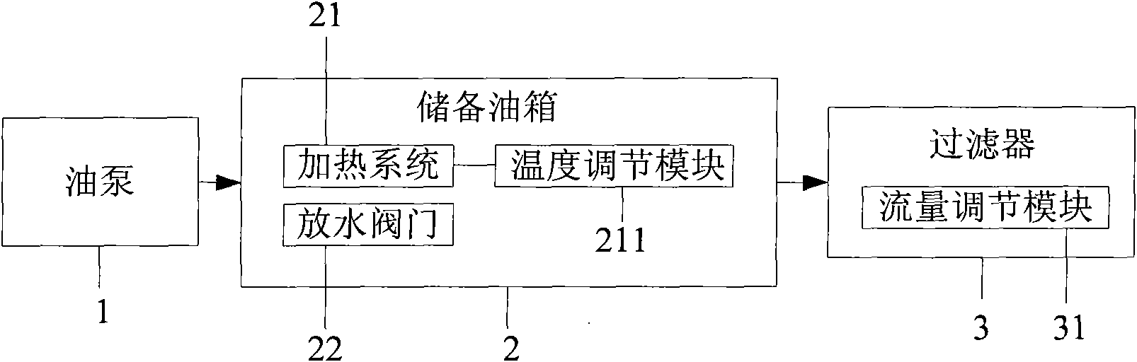
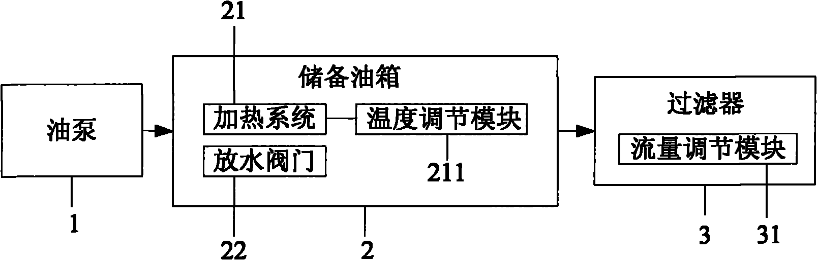
[0023] Handle the MOBIL533 lubricating oil that has been replaced from the operating system. The oil has a viscosity index of 150, a water content of 0.6%, and an impurity content of NAS15 grade. According to the above indicators of the oil to be treated, use the temperature adjustment module of the heating system to set the heating temperature in the reserve oil tank to 55°C. After the heating in the reserve oil tank and the drainage of the water release valve, the water content of the oil is reduced to 0.1%. Then the oil is subjected to ultra-fine filtration. The filtration process adopts a three-stage filtration method. The first stage uses a 40-mesh metal washable filter element, the second stage uses a 25μ filter element, and the third stage uses a 5μ filter element. The third stage uses a 5μ filter element. The filter element is an ultra-precision filter element with a strong ability to absorb moisture. Because the oil has a high viscosity and contains water, during th...


PUM


Abstract

The invention discloses an oil filter device, which comprises an oil pump, a reserve oil tank and a filter that are connected in sequence, wherein the reserve oil tank is provided with a heating system, and the bottom of the reserve oil tank is provided with a drainage valve. The invention further discloses an oil filter method. The invention can be used for carrying out on-site off-line hyperfine filter purification on waste oil to achieve the purpose of oil recycling, and thus, the oil consumption cost of enterprises is greatly reduced and an environmental-protection energy-saving effect is achieved.

Description

technical field [0001] The invention relates to an oil filter device, in particular to an oil filter device and a filter method. Background technique [0002] Oil products are widely used in industrial and mining enterprises. During use, according to the operation requirements of the equipment, the oil lubrication system is generally equipped with an online filtration system to meet the needs of the normal operation of the equipment. The purpose of the online filtration system is to ensure that the oil entering the lubrication equipment meets certain precision requirements. A series of impurities will be produced due to the inevitable friction during the operation of the equipment. In addition, water will inevitably infiltrate during the operation of the equipment. These impurities and water will eventually flow back to the oil tank for precipitation through the system. Therefore, during the operation of the equipment, more and more impurities and water will accumulate in t...

Claims


Application Information

Patent Timeline
IPC IPC(8): B01D36/00B01D37/00C10M175/00
Inventor 项铎
Owner 项铎
Why Eureka
Try Eureka