
Device and method for realizing self-stabilization of received light intensity based on laser array

A laser array and laser technology, applied in the field of laser telemetry, can solve problems such as signal distortion, detector saturation distortion, and slow response speed, and achieve high signal-to-noise ratio, fast response, and long life

Active Publication Date: 2021-05-11
HESAI TECH CO LTD
View PDF6 Cites 0 Cited by
  • Summary
  • Abstract
  • Description
  • Claims
  • Application Information

AI Technical Summary

Problems solved by technology

In the prior art, two technical solutions are mainly used to solve the technical problem of unstable laser light intensity received by the detector:
However, adjusting the exposure time of the detector will affect the response speed of the measurement equipment, such as prolonging the exposure time will cause the response speed to slow down
And if the detector is saturated and distorted due to the excessive intensity of the received laser light, even adjusting the exposure time of the detector cannot solve the problem of signal distortion

Method used


Image

  • Device and method for realizing self-stabilization of received light intensity based on laser array
  • Device and method for realizing self-stabilization of received light intensity based on laser array
  • Device and method for realizing self-stabilization of received light intensity based on laser array

Examples


Embodiment Construction

[0028] In order to make the object, technical solution and advantages of the present invention clearer, the present invention will be further described in detail below in conjunction with the accompanying drawings.

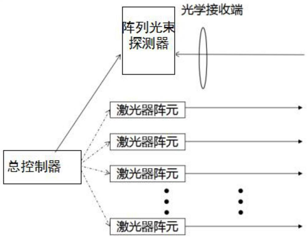
[0029] An embodiment of the present invention provides a device for realizing self-stabilization of received light intensity based on a laser array, such as figure 1 As shown, the device includes:

[0030] A laser array, the laser array is composed of a plurality of laser array elements, and the laser light emitted by each laser array element has the same wavelength and the same propagation direction.

[0031] An array beam detector, the array beam detector is used to receive the array beam emitted by the laser array, and transmit the amplitude of the received optical signal to the general controller.

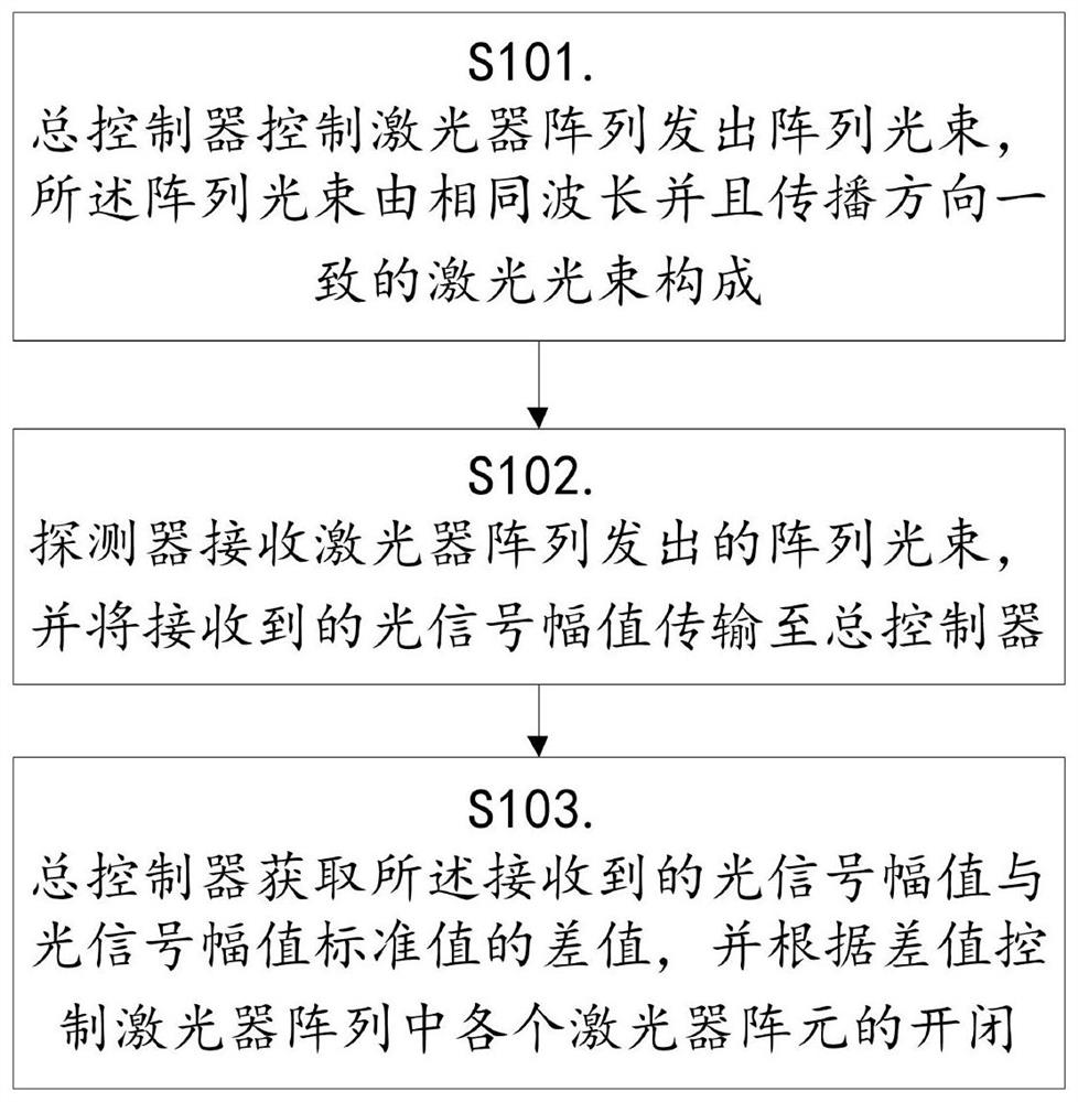
[0032] A general controller, the general controller is used to obtain the difference between the received optical signal amplitude and the standard value of the o...


PUM


Abstract

The invention provides a device and method for realizing self-stabilization of received light intensity based on a laser array. The device includes a laser array, and the laser array is composed of a plurality of laser array elements, and the laser light emitted by each laser array element has the same wavelength. and the same direction of propagation; the array beam detector is used to receive the array beam emitted by the laser array, and transmits the received optical signal amplitude to the general controller; the general controller is used to obtain the the difference between the received optical signal amplitude and the standard value of the optical signal amplitude, and control the on / off of each laser element in the laser array according to the difference. Compared with the prior art that relies on mechanical moving parts, the present invention has the advantages of fast response and long life, and does not change the performance of the optical receiving system and does not increase external stray light during the self-stabilization process of received light intensity.

Description

technical field [0001] The invention relates to the technical field of laser telemetry, in particular to a device and method for realizing self-stabilization of received light intensity based on a laser array. Background technique [0002] TDLAS is the abbreviation of Tunable Diode Laser Absorption Spectroscopy. This technology mainly uses the narrow line width and wavelength of tunable semiconductor lasers to change with the injection current to realize the measurement of single or several absorption lines that are very close and difficult to distinguish. . In the actual application of TDLAS, since the laser light intensity received by the detector is affected by many factors such as the reflectivity of the reflective surface, the laser propagation distance, the angle between the laser and the reflective surface, etc., the laser light received by the detector will Strong changes are very large. In the prior art, two technical solutions are mainly used to solve the technic...

Claims


Application Information

Patent Timeline
Patent Type & Authority Patents(China)
IPC IPC(8): G01N21/39
CPCG01N21/39G01N21/01
Inventor 陶俊向少卿
Owner HESAI TECH CO LTD
Learn More