Direct-acting fine cooling electromagnetic injection valve

A direct-acting, injection valve technology, used in injection devices, injection devices, metal rolling, etc., can solve problems such as inability to timely correct quality, increase equipment failure rates, troublesome debugging and maintenance, etc., to improve production capacity and reduce intermediate links. , Guaranteed quality effect

Inactive Publication Date: 2011-03-30
上海日森精密机械有限公司
View PDF0 Cites 8 Cited by
  • Summary
  • Abstract
  • Description
  • Claims
  • Application Information

AI Technical Summary

Problems solved by technology

The main disadvantages of this method of controlling the cooling liquid are: ① The thermal crown of the roll cannot be precisely controlled by spraying the cooling liquid flow rate according to the change of the online plate shape in time
②The control signal must first control the pneumatic solenoid valve (or use a manual valve), the pneumatic solenoid valve sends out a gas signal to control the piston pneumatic valve, and then opens the coolant valve, so there is a long delay process from signal picking to control , so that the quality of the online shape cannot be corrected in time
③Each cooling section must correspond to a set of pneumatic control system. When there are dozens of cooling sections, it will bring a lot of trouble and trouble to the installation, commissioning and daily maintenance of the equipment, which also increases the failure of the equipment. Rate
[0003] In the cold rolling process of metal steel, aluminum, copper, etc., the thermal crown of the rolling mill roll directly affects the shape of the rolled plate. In order to obtain high-quality cold-rolled strip, it is necessary to adjust the roll according to the thermal crown Fine segmental cooling of different sizes, but no technical literature reports on this aspect have been found so far

Method used


Image

  • Direct-acting fine cooling electromagnetic injection valve
  • Direct-acting fine cooling electromagnetic injection valve

Examples


Embodiment Construction

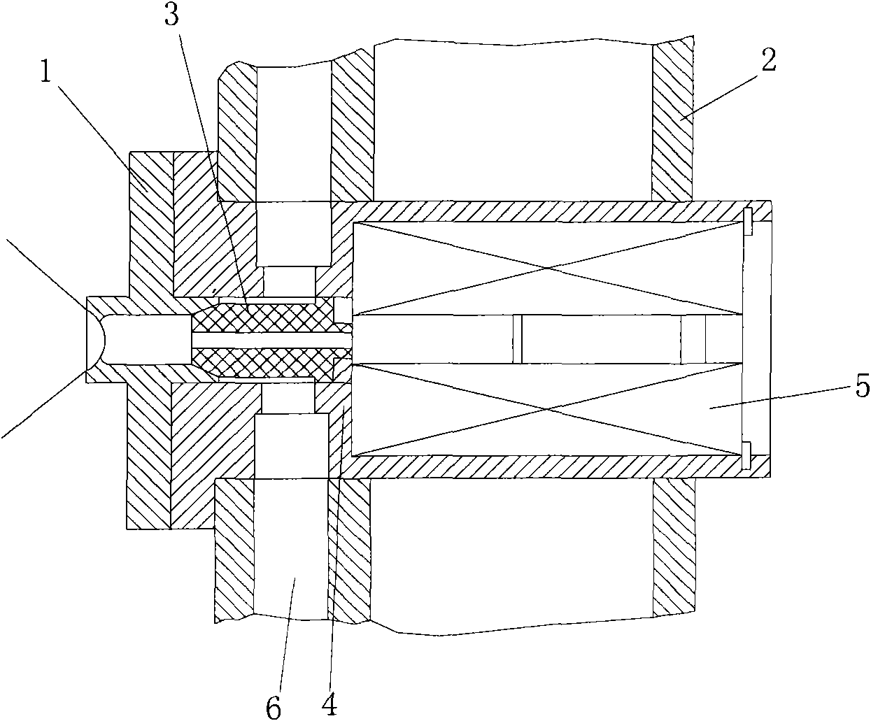
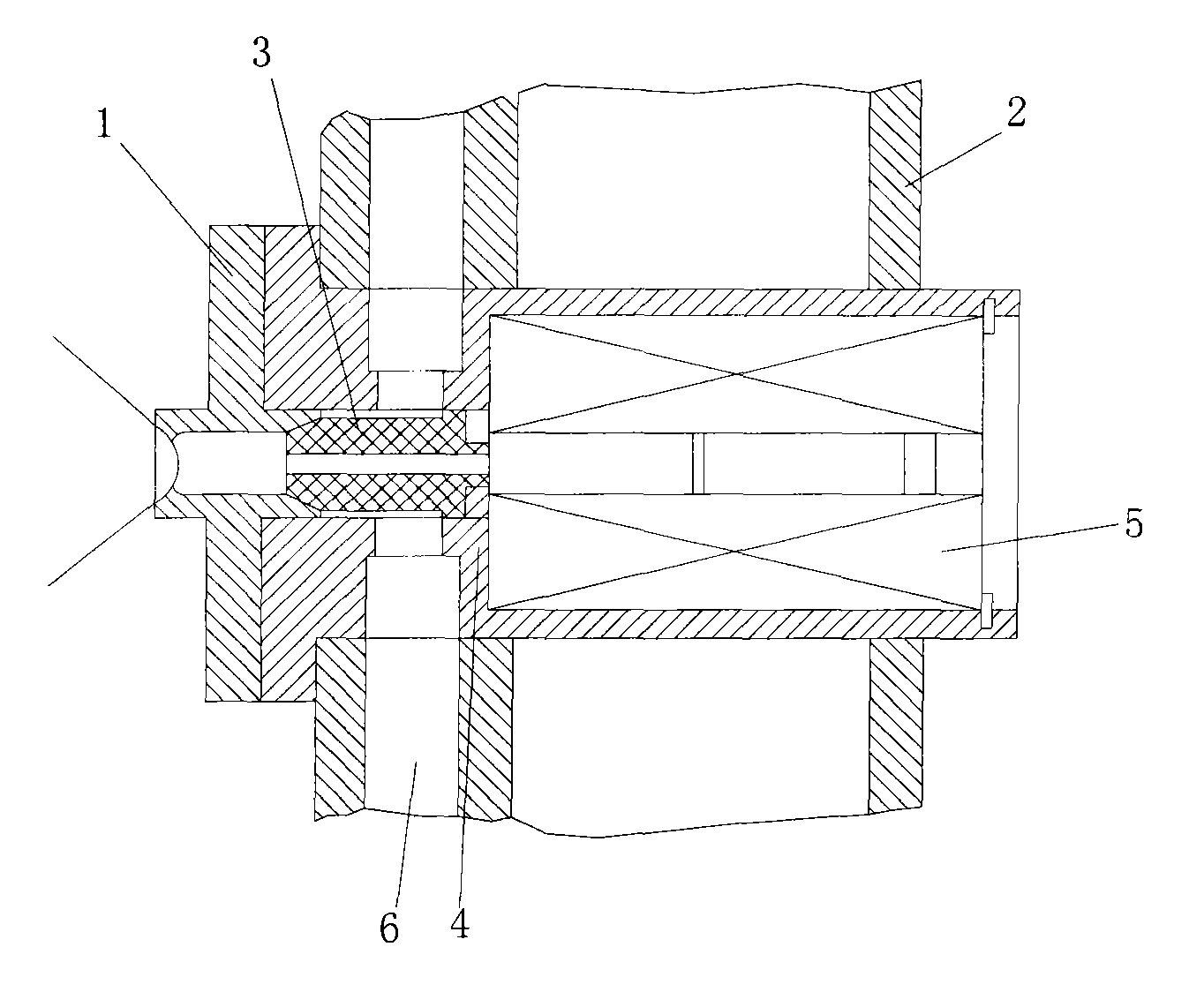
[0018] The present invention will be further described below in conjunction with the accompanying drawings.

[0019] Such as figure 1 Shown is a schematic structural view of the direct-acting fine cooling electromagnetic injection valve of the present invention, including an injection nozzle assembly 1 , a spray beam 2 , a valve core 3 , a valve body 4 , an electromagnet assembly 5 , and a coolant 6 . The spray nozzle assembly 1 is composed of a spray nozzle body and a spray nozzle. It can choose a suitable nozzle angle and flow rate according to the user's coverage requirements for the cooling of the roll surface. The spray beam 2 is the base organically connected with the rolling mill, which fixes the solenoid valve and provides a sufficient amount of coolant carrier. The spool 3 is made of heat-resistant, corrosion-resistant, and non-deformable imported sealing material, which has the function of opening and closing the cooling liquid output. The valve body 4 is an integr...


PUM


Abstract

The invention discloses a direct-acting fine cooling electromagnetic injection valve used for cooling a cold rolling band plate roller, comprising an injection nozzle assembly, an injection beam, a valve plug, a valve body, an electromagnet assembly and cooling liquid, wherein the electromagnet assembly and the valve plug are installed to be combined into the valve body; a solenoid-type structure is adopted by the electromagnet assembly; the injection nozzle assembly comprises an injection nozzle body and an injection nozzle; the injection beam is a base which is organically connected together with a rolling mill; and the valve plug is made of heat-resistant and corrosion-resistant non-deformable imported sealing materials. In the invention, the electromagnetic valve is directly controlled by an online plate-shaped electrical signal, and the flow of the cooling liquid ejected from the ejection valve in the unit time is accurately regulated through regulating the pulse width of the electrical signal; the thermal convexity of the roller is regulated through sectionally cooling the roller, thereby accurately solving the problem of the thermal convexity of the online roller in different sections, ensuring the quality of the cold rolling band plate and improving the linear rolling speed of the rolling mill.

Description

technical field [0001] The invention relates to an electromagnetic injection valve, in particular to a direct-acting fine cooling electromagnetic injection valve. Background technique [0002] At present, a pneumatic solenoid valve or a manual air valve is used to control a piston-type control valve to open the coolant valve in the strip cold rolling process. The disadvantages of this method of controlling the cooling liquid mainly include: 1. The thermal crown of the roll cannot be precisely controlled by spraying the cooling liquid flow rate according to the change of the online plate shape in time. ②The control signal must first control the pneumatic solenoid valve (or use a manual valve), the pneumatic solenoid valve sends out a gas signal to control the piston pneumatic valve, and then opens the coolant valve, so there is a long delay process from signal picking to control , so that the quality of the online shape cannot be corrected in time. ③Each cooling section mus...

Claims


Application Information

Patent Timeline
Patent Type & Authority Applications(China)
IPC IPC(8): B21B27/10B21B37/32B05B1/30B05B12/00
Inventor 黄芸
Owner 上海日森精密机械有限公司
Why Eureka
Try Eureka