Trapped vortex tail wing carburetor of throttle

A technology of throttle valve and carburetor, which is applied in the field of throttle valve vortex tail carburetor, can solve the problems of combustion chamber intake pressure loss and other problems, and achieve the effect of small pressure loss and high mixing degree

Inactive Publication Date: 2011-03-30
张龙
View PDF0 Cites 1 Cited by
  • Summary
  • Abstract
  • Description
  • Claims
  • Application Information

AI Technical Summary

Problems solved by technology

However, the airflow separation caused by the sudden vertical expansion of the passage area behind the throttle valve of the carburetor leads to a large loss of the intake pressure of the combustion chamber, but the vortex generated by the airflow separation is conducive to the mixing of fuel, so it not only forms the airflow vortex but also reduces the separation intensity It is an important factor to determine the combustion efficiency of the engine

Method used


Image

  • Trapped vortex tail wing carburetor of throttle
  • Trapped vortex tail wing carburetor of throttle
  • Trapped vortex tail wing carburetor of throttle

Examples


Embodiment Construction

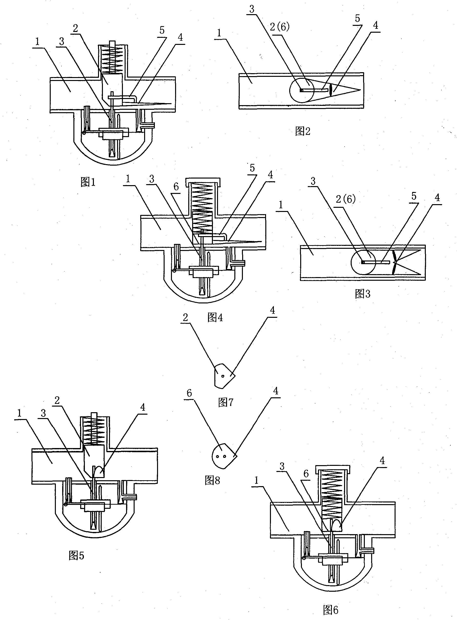
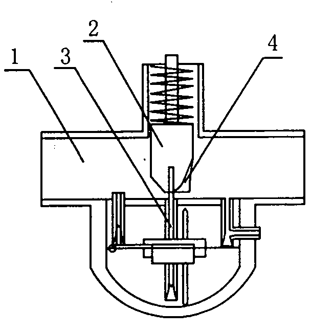
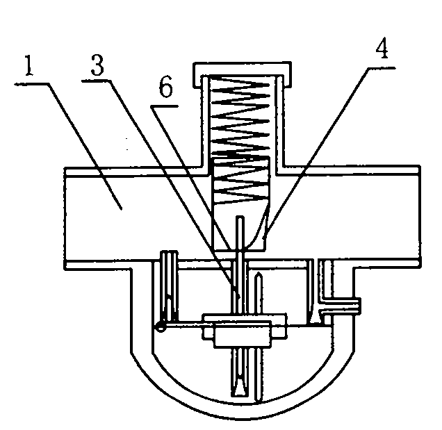
[0018] exist figure 1 and figure 2 or image 3 In the plunger type throttle valve vortex tail carburetor shown in the two embodiments shown, the vortex tail (4) is installed behind the plunger throttle (2) in the carburetor body assembly (1), and the vortex tail The bottom surface of (4) is flush with the bottom surface of the plunger throttle (2), and the initial width of the single-tail empennage both sides edges of the first embodiment is equal to the diameter of the plunger throttle (2) or the width of the air passage, and the root is equal to that of the plunger throttle (2). The rear wall of the plunger throttle (2) is attached, and the edges on both sides of the empennage start from the root as straight lines, elliptical lines or arcs intersect at the tail tip, and the cross-section of the empennage is an arc or an edge line with a straight line, the second The double-tailed (dovetail) empennage of embodiment then adds two edges and expands from the middle of the rea...


PUM


Abstract

The invention provides a trapped vortex tail wing carburetor of a throttle. In the invention, a trapped vortex tail wing (4) is additionally arranged below or behind a plunger throttle (2) or a diaphragm throttle (6) in a carburetor body assembly (1), through vortex shedding and the swept effect of a trapped vortex of the trapped vortex tail wing (4) of the throttle, after an air flow flows around to a low pressure region behind the throttle, the loss is lowered, and secondary rotational speed of a mixed gas is formed, thereby increasing the power and the combustion efficiency of an engine, and reaching the purpose of saving fuel oil.

Description

Technical field [0001] The invention belongs to the field of automobile and motorcycle engine parts, and relates to a throttle valve vortex tail carburetor. Background technique [0002] At present, there are two types of carburetors for automobile and motorcycle engines: plunger carburetors and equal-vacuum diaphragm carburetors. No matter what kind of carburetor, its working principle is to rely on the vacuum generated by the movement of the engine piston to suck air from the air intake of the carburetor through the throat of the carburetor throttle, and the pressure difference generated to make the liquid fuel flow from the carburetor float. The air is sucked out of the chamber, and the mixed gas is formed by high-speed airflow impact atomization and enters the combustion chamber for combustion. However, the airflow separation caused by the sudden vertical expansion of the passage area behind the throttle valve of the carburetor leads to a large loss of the intake pressu...

Claims


Application Information

Patent Timeline
Patent Type & Authority Applications(China)
IPC IPC(8): F02M7/12
Inventor 张龙
Owner 张龙
Why Eureka
Try Eureka