Method for measuring transmission loss of optical element

A technology of optical components and measurement methods, which is applied in the direction of transmittance measurement and optical performance testing, etc., can solve difficult problems such as optical component measurement, achieve high signal-to-noise ratio and improve measurement accuracy

Active Publication Date: 2011-03-30
INST OF OPTICS & ELECTRONICS - CHINESE ACAD OF SCI
View PDF6 Cites 16 Cited by
  • Summary
  • Abstract
  • Description
  • Claims
  • Application Information

AI Technical Summary

Problems solved by technology

[0006] All of the above methods have certain size requirements for the optical components to be tested, and it is difficult to measure optical components with small aper...

Method used


Image

  • Method for measuring transmission loss of optical element
  • Method for measuring transmission loss of optical element
  • Method for measuring transmission loss of optical element

Examples


Embodiment Construction

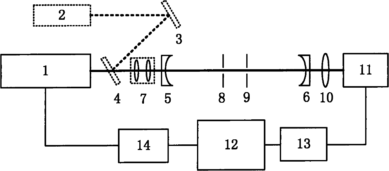
[0042] Attached below figure 1 The described system describes the method for measuring transmission loss of an optical element of the present invention. figure 1 Middle: 1 is the light source, 2 is the visible auxiliary light source, 3 is the reflector, 4 is the double-beam beam splitter, 5 and 6 are the plano-concave high-reflection cavity mirror, 7 is the mode matching lens group, 8 and 9 are the iris diaphragm 10 is a focusing lens, 11 is a photodetector, 12 is a computer, 13 is a data acquisition card, and 14 is a function generation card. Among the figures, thick lines are optical paths, and thin lines are connection lines.

[0043] The light source 1 is a continuous semiconductor laser, and the semiconductor laser adopts a 100Hz square wave modulation output; two identical flat-concave high-reflection cavity mirrors 5 and 6 have a reflectivity greater than 99% at the wavelength of the laser, and the optical resonator is a stable cavity or a confocal cavity. The length L...


PUM


Abstract

The invention relates to a method for measuring transmission loss of an optical element. The method comprises the following steps that: continuous laser is reshaped through a mode matching lens, and then enters an optical resonant cavity along an optical axis; two iris diaphragms of which the standoff distance is slightly larger than the thickness of the optical element to be measured are placed into the optical resonant cavity, wherein the clear aperture is less than the aperture of the optical element to be measured; after a shutoff laser beam is triggered, an output signal of the optical resonant cavity is recorded to fit fading time tau 0; the optical element to be measured is placed between the two iris diaphragms in the optical resonant cavity; the optical element to be measured is adjusted to make the surface of the optical element vertical to the optical axis; the output signal of the optical resonant cavity is recorded to fit fading time tau 1; the angle of the optical element to be measured is adjusted to make directly reflected light on the surface escape from the optical resonant cavity; the output signal of the optical resonant cavity is recorded to fit fading time tau 2; the absorption loss A of the optical element to be measured can be acquired by using the tau 0 and the tau 1; and the surface antireflective film residual reflectance R of the optical element to be measured is acquired by using the tau 1 and the tau 2. The method has the advantages of simple structure, high measurement precision, low system cost and the like.

Description

technical field [0001] The invention relates to a method for measuring the transmission loss of an optical element, in particular to a method for measuring the transmission loss of a small-diameter optical element. Background technique [0002] With the continuous development of coating technology, the transmittance of anti-reflection coating has been continuously improved. In complex optical systems, dozens or even hundreds of high-transmittance optical components coated with anti-reflection coatings are often used. The quality of the anti-reflection coatings coated on optical components plays a vital role in the performance of the entire system. It is very important to test the residual reflectivity of the anti-reflection coating on the surface of the high transmittance optical element and the absorption loss of the transmission optical element. In recent years, micro-miniature optical systems are also developing continuously, the degree of miniaturization of optical comp...

Claims


Application Information

Patent Timeline
IPC IPC(8): G01M11/02G01N21/59
Inventor 李斌成曲哲超韩艳玲
Owner INST OF OPTICS & ELECTRONICS - CHINESE ACAD OF SCI
Why Eureka
Try Eureka