
Remote monitoring method and system for development machine

A remote monitoring system and remote monitoring technology, applied in electrical program control, earthwork drilling, comprehensive factory control, etc., can solve unfavorable roadheader rapid fault diagnosis, accident handling and remote monitoring management, high labor intensity of drivers, and poor comfort and other issues to achieve the effect of improving safe and reliable operation capabilities

Inactive Publication Date: 2012-06-13
CHINA UNIV OF MINING & TECH
View PDF0 Cites 0 Cited by
  • Summary
  • Abstract
  • Description
  • Claims
  • Application Information

AI Technical Summary

Problems solved by technology

However, in the mining process of coal mine roadway, the dust is relatively large, and the operator of the roadheader cannot see the actual position of the cutting head, which causes under-excavation and over-excavation phenomena. Under-excavation brings secondary excavation, and over-excavation brings support and Increased backfill workload
Because most of the equipment is manually operated, the driver's labor intensity is high, the comfort is poor, the labor productivity is low, and the construction quality and construction safety largely depend on human factors, the number of underground casualties is still high
The traditional monitoring system has a limited amount of monitoring data, and most of them are transmitted by cables. The real-time performance is poor and there are few monitoring areas for the operation status of the whole machine, which is not conducive to rapid fault diagnosis, accident handling and remote monitoring management of the roadheader.

Method used


Image

  • Remote monitoring method and system for development machine
  • Remote monitoring method and system for development machine
  • Remote monitoring method and system for development machine

Examples


Embodiment Construction

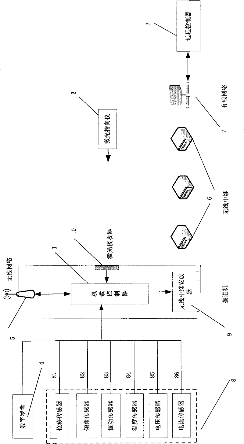
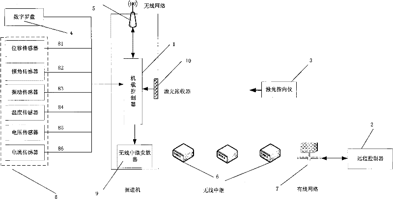
[0015] In order to realize the roadheader remote monitoring method and system of the present invention, it includes: on-board controller, remote controller, laser pointer, digital compass, wireless network, wireless relay, wired network, distributed sensor network, wireless relay Placement device, laser receiver.

[0016] The distributed sensor network is composed of displacement sensors, inclination sensors, temperature sensors, voltage sensors, current sensors and vibration sensors. Monitor the running status of the roadheader comprehensively in real time, and transmit the data to the onboard controller through the field bus; the laser pointing device is used to emit laser beams for precise positioning in the roadway of the roadheader, and is used in pair with the laser receiver ; The laser receiver can capture the light on the laser beam surface, and input the signal to the onboard controller through the field bus; the wireless network can complete the sending and receiving...


PUM


Abstract

The invention discloses a remote monitoring method and a remote monitoring system for a development machine, which are used for local and remote real-time monitoring of development process, working state and dynamic parameters of the development machine, high-speed wireless data transmission, information acquisition, finishing and storage and have remote monitoring function. The system comprises an onboard controller, a remote controller, a laser orientation instrument, a laser receiver, a digital compass, a wireless network, a wireless repeater, a wired network, a distributed sensor network and a wireless repeater placer. By adopting a wired and wireless data transmission mode, the method and the system well solve the problems of coal bed falling rock, cable dragging damage and the like because a mechanical cable winding system is adopted in the traditional data transmission. The remote monitoring method and the remote monitoring system for the development machine can instantly, intuitively, accurately and comprehensively reflect the running states of the development machine in the onboard controller and the remote controller, perform fault diagnosis and remote control and improve the safe and reliable running capability of the development machine by digital and information means.

Description

technical field [0001] The present invention relates to remote monitoring of roadheaders, specifically a device that can provide local and remote real-time monitoring of the roadheader's tunneling process, working status and dynamic parameters, high-speed wireless data transmission, information collection, sorting and storage, and remote fault diagnosis and monitoring functions. A roadheader remote monitoring method and system. Background technique [0002] The roadheader has the advantages of high production efficiency, fast tunneling speed, strong adaptability, and flexible mobilization, and has become a necessary production equipment for coal mines. However, during the mining process of coal mine roadway, the dust is relatively large, and the operator of the roadheader cannot see the actual position of the cutting head, which causes under-excavation and over-excavation phenomena. Under-excavation brings secondary excavation, and over-excavation brings support and Increas...

Claims


Application Information

Patent Timeline
Patent Type & Authority Patents(China)
IPC IPC(8): G05B19/418E21D9/00
Inventor 童敏明童紫原薛夫振唐守锋
Owner CHINA UNIV OF MINING & TECH
Learn More