Silicon tetrachloride hydrogenation reactor introducing microcirculation distribution structure

The technology of a hydrogenation reactor and silicon tetrachloride is applied in the directions of halogenated silicon compounds, halogenated silanes, etc., which can solve the problems of large number of low-speed fluidized bubbles and large back-mixing degree, limited one-pass conversion rate, and high comprehensive energy consumption. Achieve the effect of increasing the gas-solid contact area, improving the single-pass conversion rate, and optimizing the internal structure

Active Publication Date: 2011-04-06
TIANJIN UNIV
View PDF4 Cites 5 Cited by
  • Summary
  • Abstract
  • Description
  • Claims
  • Application Information

AI Technical Summary

Problems solved by technology

The fixed bed reactor has the advantages of simple structure, small back mixing, and small loss of catalyst, but it has obvious disadvantages, such as poor heat transfer effect, inconvenient catalyst replacement and regeneration, and large space required when production requirements are large. Continuous production cannot be carried out, and comprehensive energy consumption is high
The fluidized bed reactor can solve these problems very well and realize the continuous production of the hydrogenation process of silicon tetrachloride. In recent years, major domestic polysilicon enterprises have con

Method used


Image

  • Silicon tetrachloride hydrogenation reactor introducing microcirculation distribution structure
  • Silicon tetrachloride hydrogenation reactor introducing microcirculation distribution structure
  • Silicon tetrachloride hydrogenation reactor introducing microcirculation distribution structure

Examples


Example Embodiment

[0017] The present invention will be further explained below with the accompanying drawings, which are drawn to illustrate the present invention and do not limit the specific application form of the present invention.
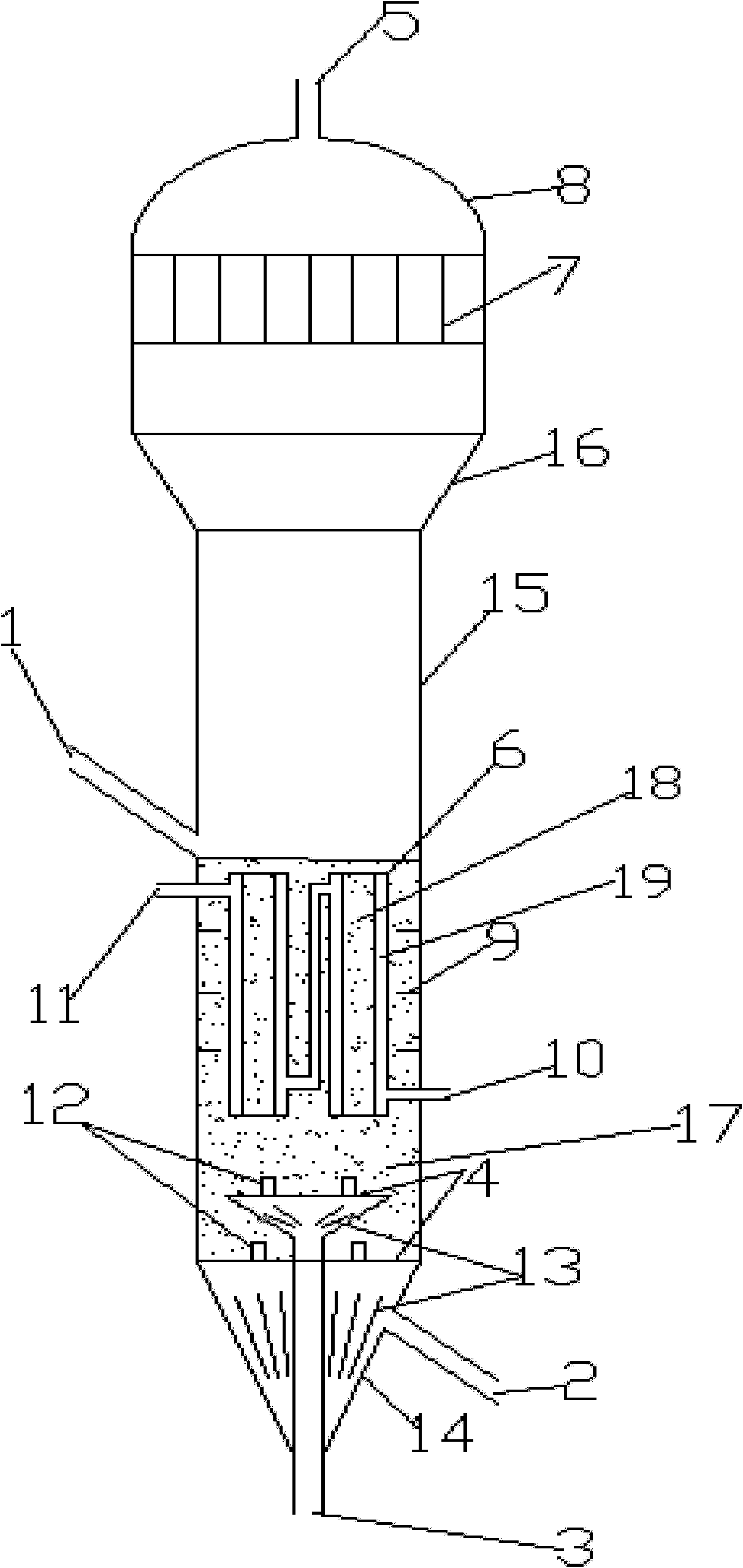
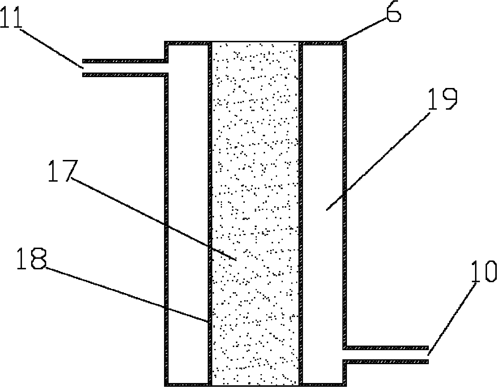
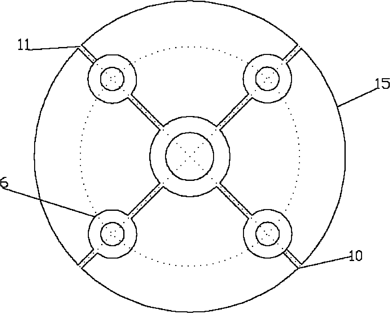
[0018] The present invention is a silicon tetrachloride hydrogenation reactor with microcirculation distribution structure, such as figure 1 Shown: Including silicon powder inlet 1, hydrogen inlet 2, silicon tetrachloride inlet 3, gas distribution plate 4, post-reaction gas outlet 5, heat exchange tube bundle 6, filter tube bundle 7, and elliptical head 8 , Horizontal baffle 9, heat conduction oil inlet 10, heat conduction oil outlet 11, side slit cone cap 12, gas pre-distributor 13, lower cone section 14, cylindrical shell 15, variable diameter section 16, catalyst particles and metallurgical grade The bed 17 formed by mixing silicon powder, the hollow pipe 18 of the heat exchange tube and the jacket 19 of the heat exchange tube. After the metallurgical grade sil...


PUM


Abstract

The invention discloses a silicon tetrachloride hydrogenation reactor introducing a microcirculation distribution structure, comprising a lower tapered section, a reaction section, a reducing section, a gas-solid separating section and an end enclosure, wherein a heat exchange pipe bundle is arranged in the reaction section and comprises the structure that heat exchange tubes with the same diameter are uniformly distributed around a center heat exchange tube; and the diameter of the center heat exchange tube is greater than that of the heat exchange tubes distributed around; the heat exchange tubes are dual-layer metal conduits; heat-conducting oil flows in clamping sleeves of the heat exchange tubes; and the hollow conduits are in direct contact with particles on a bed layer inside a fluidized bed. The microcirculation distribution structure is introduced into the silicon tetrachloride hydrogenation reactor; the hollow conduits are in direct contact with particles on the bed layer inside the fluidized bed; the diameters of the hollow conduits are far smaller than the diameter of a fluidized bed reactor; gas has higher flow speed in the hollow conduits to drive solid particles to accelerate the movement so as to form an internal circulation; the miniature circulating fluidization can be formed in a bear area of each heat exchange tube, benefits the crushing of air bubbles in the gas-solid reaction, simultaneously reduces the phenomenon of gas backmixing and improves the per pass conversion of silicon tetrachloride to about 32 percent.

Description

technical field [0001] The present invention is a silicon tetrachloride hydrogenation reactor which introduces a microcirculation distribution structure. The reactor is a fluidized bed reactor, which is mainly used in the formation of trichloride from silicon tetrachloride, silicon powder and hydrogen under the action of a certain catalyst. Chlorosilane reaction. Background technique [0002] Polysilicon is the main raw material for manufacturing integrated circuit substrates, solar cells and other products, and is widely used in the semiconductor industry. At present, the mainstream production process of polysilicon in Chinese enterprises is the improved Siemens method, and its typical process is as follows: Synthesize hydrogen chloride with chlorine and hydrogen, synthesize trichlorosilane at a certain temperature with hydrogen chloride and industrial silicon powder, and simultaneously generate silicon tetrachloride and other by-products. product, and then carry out recti...

Claims


Application Information

Patent Timeline
IPC IPC(8): C01B33/107
Inventor 黄国强毛俊楠王红星华超苏国良
Owner TIANJIN UNIV
Why Eureka
Try Eureka