Capacity loaded magnetic flux compression generator with stator coil operating sectionally

A stator coil and capacitive load technology, which is applied in blasting and other directions, can solve the problem of low frequency range of the signal spectrum, achieve the effect of increasing the frequency band, increasing the signal bandwidth, and increasing the signal frequency

Inactive Publication Date: 2013-03-27
HARBIN INST OF TECH
View PDF5 Cites 0 Cited by
  • Summary
  • Abstract
  • Description
  • Claims
  • Application Information

AI Technical Summary

Problems solved by technology

[0006] The purpose of the present invention is to solve the problem that the frequency band of the signal spectrum range produced by the existing capacitive load solenoid type detonation magnetic compression generator is low, and to provide a capacitive load detonation magnetic compression generator with segmental work of the stator coil

Method used


Image

  • Capacity loaded magnetic flux compression generator with stator coil operating sectionally
  • Capacity loaded magnetic flux compression generator with stator coil operating sectionally
  • Capacity loaded magnetic flux compression generator with stator coil operating sectionally

Examples


specific Embodiment approach 1

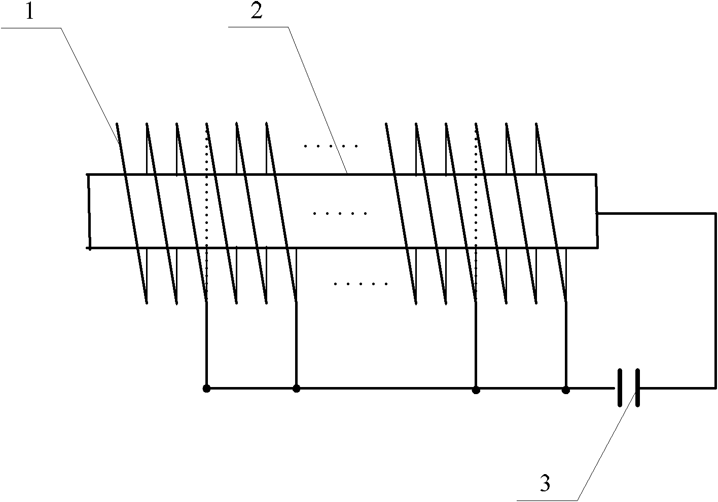
[0016] Specific implementation mode 1: the following combination Figure 1 to Figure 4 Explaining this embodiment, the capacitive load blasting magnetization compression generator with stator coil segmented operation described in this embodiment includes a stator coil 1, an armature 2 and a capacitive load 3.

[0017] The armature 2 is a cylindrical body, the stator coil 1 is divided into n-segment coils, the n-segment coils of the stator coil 1 are all spiral-shaped, and the armature 2 is arranged in the internal cavity formed by the n-segment coils, And each coil is coaxial with the armature 2. From the beginning of the armature 2, the end of each adjacent previous coil and the beginning of the subsequent coil are located on the same cross section of the armature 2, and the end of each coil Both are connected to one end of the capacitive load 3, and the end of the armature 2 is connected to the other end of the capacitive load 3.

[0018] The starting end of the armature 2 is th...

specific Embodiment approach 2

[0024] Specific implementation manner 2: the following combination figure 1 This embodiment is described. This embodiment is a further explanation of the first embodiment. Each stator coil 1 has a constant pitch, and the pitch of adjacent stator coils 1 increases geometrically from the beginning of the armature 2. Other components and connection relationships are the same as in the first embodiment.

[0025] The loss caused by the Joule heat of the resistance is very serious, especially at the end of the operation of the capacitive load blasting compression generator, because the current and current density are very large at this time. The winding method of the stator coil 1 with variable pitch can partially solve this problem. It can avoid a large number of Joules caused by unlimited increase in current density by increasing the cross-sectional area of ​​the corresponding section of the stator coil 1 at the end of the generator to maintain the current density at a constant accep...


PUM


Abstract

The invention discloses a capacity loaded magnetic flux compression generator with a stator coil operating sectionally, belonging to the fields of high-power pulse power sources and magnetic compression. By utilizing the capacity loaded magnetic flux compression generator of the invention, the problem of lower frequency range of signal spectral range generated by the existing capacity loaded helical magnetic flux compression generator is solved. The capacity loaded magnetic flux compression generator of the invention comprises the stator coil, an armature and a capacitive load, wherein the armature is a cylinder; the stator coil is divided into n numbered coils, and the n numbered coils of the stator coil are helical; the armature is arranged in an inner cavity formed by the n numbered coils, all the coils have the same coaxial line with the armature; from the initial end of the armature, in terms of every two adjacent coils, the tail end of the front coil and the head end of the rear coil are positioned on the same cross section of the armature; the tail ends of all the coils are connected with one end of the capacitive load; and the tail end of the armature is connected with the other end of the capacitive load. The invention is suitable for magnetic flux compression generators.

Description

Technical field [0001] The invention relates to a capacitive load blast magnetization compression generator with stator coils working in sections, belonging to the field of high-power pulse power supplies and magnetic compression. Background technique [0002] The magnetic blast compression generator is a pulse-type, inductive energy supply system developed in the late 1950s. It has a series of advantages such as small size, high energy storage density, deformable design, and low manufacturing cost. As a pulsed power source, the blast magnet compression generator is only an energy amplification device, and it also needs energy supply. Generally speaking, it has two energy systems. The initial energy provides the initial magnetic flux as a seed source to form the magnetic flux distribution to be compressed; while the high-energy explosive provides power consumption for it. The chemical energy released by the explosive drives the metal sleeve to expand and overcome the force of th...

Claims


Application Information

Patent Timeline
Patent Type & Authority Patents(China)
IPC IPC(8): F42D1/045
Inventor 李红梅韩颖超邱景辉宋朝晖
Owner HARBIN INST OF TECH
Why Eureka
Try Eureka