
Infrared focal plane array detector simulation device and method

A technology of array detectors and infrared focal planes, applied in measuring devices, radiation pyrometry, instruments, etc., can solve the problem of inability to respond to signals of infrared focal plane array detectors, cumbersome operating procedures and equipment, and inability to generate infrared image information Problems such as detector signals, to speed up development progress, reduce development costs, and shorten development weeks

Active Publication Date: 2011-04-06
NANJING UNIV OF SCI & TECH
View PDF5 Cites 26 Cited by
  • Summary
  • Abstract
  • Description
  • Claims
  • Application Information

AI Technical Summary

Problems solved by technology

[0010] In the Chinese invention patent "Simulation Method and Device for Infrared Detector Output" (CN 101425098A), Wang Ende et al. invented a method and device for simulating infrared detector output, which involves simulating the detector based on target motion information and target position information The waveform information is used as the output of the infrared detector, but it is only for the four-element infrared detector, and it is not suitable for the large-scale infrared focal plane array detectors, such as 320×256, 384×288, 640×480, For detectors with specifications such as 1024×1024, the technology disclosed in this patent cannot effectively simulate the response signal of the infrared focal plane array detector
[0011] In the Chinese invention patent "Device and method for simulating infrared detector output signal" (CN100498806C), Zhang Yong and others invented a device and method for simulating infrared detector output signal. The pre-development of processing provides real simulation data", but it can only provide simulation data signals for the back-end processing system, it cannot detect and judge the driving signal provided by the driving circuit and feed back the information of the driving signal, and it cannot be confirmed when the driving signal is correct. The output of the infrared focal plane array detector response signal containing infrared scene information cannot accurately simulate the phase information in the detector response signal. There are deficiencies in the verification of the back-end signal processing circuit, and it cannot be completely used in the debugging process of the infrared imaging system. Instead of real detectors, it is necessary to develop a simulation device and method that can completely replace real detectors during the development and debugging of infrared imaging systems
[0012] In the document "Design and Implementation of Infrared Detector Simulator" ("Infrared and Laser Engineering" June 2008 Supplement Volume 37), Zhao Yuyin and Ling Jianguo described the design and implementation of an infrared detector simulator. The method The detector signal of the infrared scene can be generated, but this design still uses a multimeter and an oscilloscope to detect the power supply voltage. The operating procedures and equipment are relatively cumbersome, and it cannot detect and judge the driving signal provided by the driving circuit and feed back the information of the driving signal. Every time an integrated signal is received, after delaying several detector inherent delay periods, the analog level of the pixel is sequentially output under the drive of the master clock." More importantly, this scheme can only simulate a static infrared scene information. Detector signal, detector signal that cannot generate continuous motion infrared image information
It produces an analog signal that only contains a static infrared image, which does not play a role in verifying the back-end image processing algorithm, and cannot truly simulate the response signal of the infrared focal plane array detector. It exists when verifying the signal processing circuit. Obvious deficiency

Method used


Image

  • Infrared focal plane array detector simulation device and method
  • Infrared focal plane array detector simulation device and method
  • Infrared focal plane array detector simulation device and method

Examples


Embodiment Construction

[0029] The present invention will be described in further detail below in conjunction with the accompanying drawings.

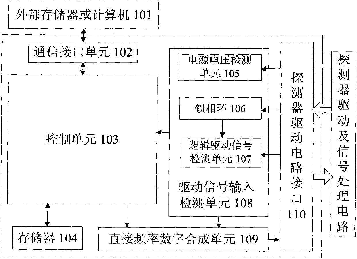
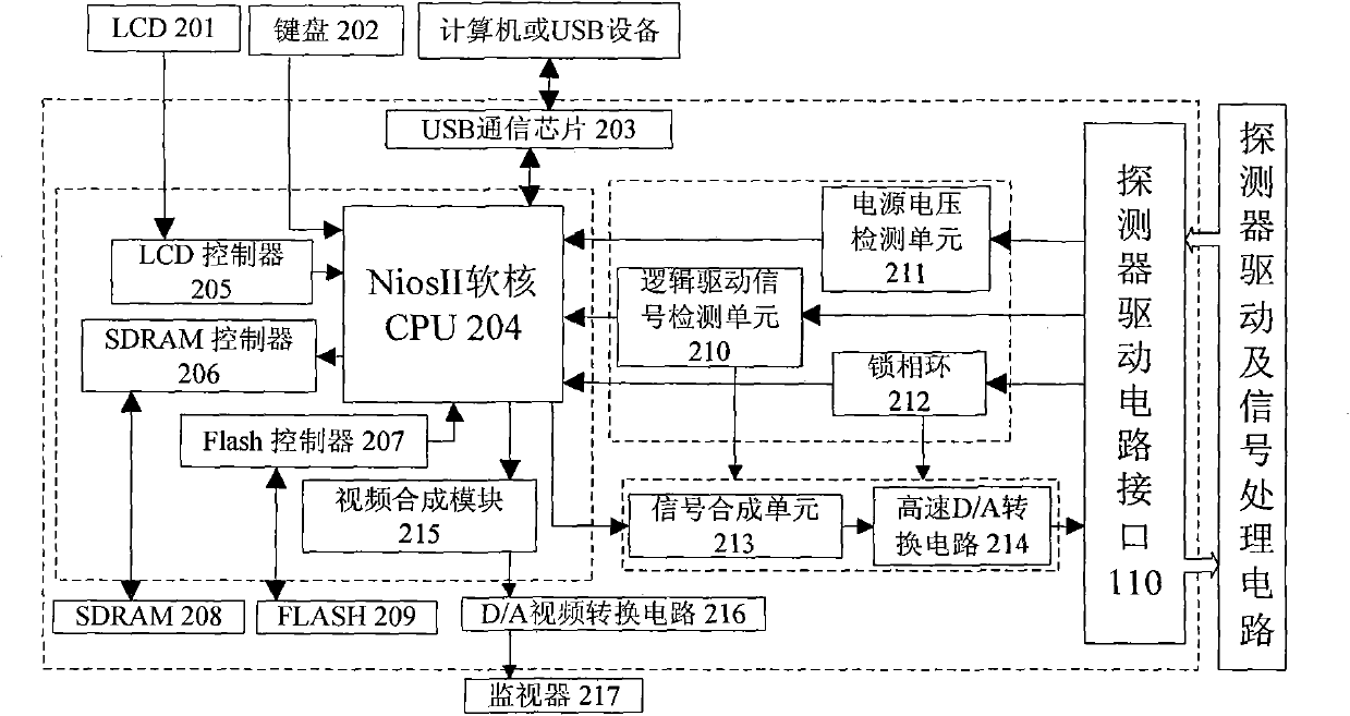
[0030] The present invention proposes an infrared focal plane array detector simulation device, including a communication interface unit 102, a control unit 103, a memory 104, a drive signal input detection unit 108, a direct digital frequency synthesis unit 109, and a detector drive circuit interface 110,

[0031] The signal acquisition port of the drive signal input detection unit 108 is connected to the detector drive circuit through the probe drive circuit interface 110, and the signal output port of the drive signal input detection unit 108 is directly connected to the signal input of the control unit 103 and the direct digital frequency synthesis unit 109 interface,

[0032] The signal output interface of the direct digital frequency synthesis unit 109 is connected to the signal acquisition interface of the detector signal processing circuit through the...


PUM


Abstract

The invention discloses an infrared focal plane array detector simulation device and an infrared focal plane array detector simulation method. The device comprises a communication interface unit, a control unit, a storage, a driving signal input and detection unit, a direct digital frequency synthesis unit and a detector driving circuit interface, wherein the driving signal input and detection unit acquires driving signals from a detector driving circuit through the detector driving circuit interface; the control unit judges whether the signals meet the requirement of an infrared focal plane array detector; when the driving signals are absolutely right, the control unit reads infrared scene information in the storage or infrared scene information output through the communication interface, and outputs the infrared scene information to the direct digital frequency synthesis unit; and the infrared scene information is synthesized into analog signals according to a rule of detector response signals and then is output. The infrared focal plane array detector simulation device can replace an actual infrared focal plane array detector in the early stage of debugging an infrared imaging system, and can detect the driving signals of the driving circuit and feed information back; and the development schedule is accelerated and the development cost is reduced.

Description

technical field [0001] The invention relates to the field of infrared focal plane array imaging system technology and signal simulation, in particular to a device for generating response signals of infrared focal plane array detectors, which is applied to the field of development and debugging of infrared focal plane array detector imaging systems. Background technique [0002] As the requirements for optoelectronic technology in various fields such as national defense and industry are getting higher and higher, infrared imaging systems are being used more and more. The infrared focal plane array detector is the core device of the infrared imaging system, whether it is a cooled infrared focal plane array detector or an uncooled infrared focal plane array detector, it is expensive. [0003] In the design, development and production of infrared imaging systems, direct use of infrared focal plane array detectors is essential. For example, during the debugging process of the in...

Claims


Application Information

Patent Timeline
IPC IPC(8): G01R31/28H04N17/00G01J5/00
Inventor 张俊举常本康夏朋浩张宝辉钱芸生
Owner NANJING UNIV OF SCI & TECH
Learn More