Organic electroluminescent device taking metal and P-type disc-shaped compound as composite anode

An electroluminescent device and luminescence technology, which is applied in the direction of electric solid-state devices, electrical components, semiconductor devices, etc., can solve the problems of high material cost and high energy consumption of ITO anodes

Inactive Publication Date: 2011-04-06
西安文景光电科技有限公司
View PDF4 Cites 9 Cited by
  • Summary
  • Abstract
  • Description
  • Claims
  • Application Information

AI Technical Summary

Problems solved by technology

[0015] The object of the present invention is to solve the problems of large energy consumption and high material cost of ITO anode in organic electroluminescent devices, and to provide an organic electroluminescent device with metal and P-type discotic compound as composite anode, so that it has good power saving high performance and low material cost

Method used


Image

  • Organic electroluminescent device taking metal and P-type disc-shaped compound as composite anode
  • Organic electroluminescent device taking metal and P-type disc-shaped compound as composite anode
  • Organic electroluminescent device taking metal and P-type disc-shaped compound as composite anode

Examples


Embodiment 1

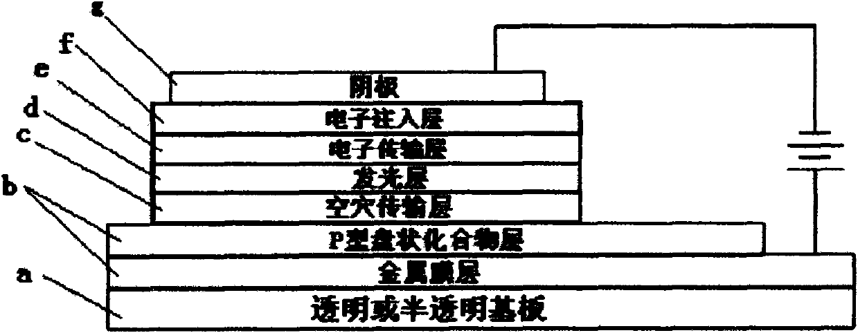
[0038] see figure 1 , an organic electroluminescence device made with the composite anode provided by the invention has a multilayer structure, and the multilayer structure can be in the following order:

[0039] a. Transparent or translucent substrate

[0040] b. Composite anode

[0041] c. Hole transport layer

[0042] d. Emissive layer

[0043] e. Electron transport layer

[0044] f. Electron injection layer

[0045] g. Cathode

[0046] The substrate a in this example is made of flat glass, the composite anode b is formed of aluminum (Al) and the P-type discotic organic compound HATCN represented by chemical formula 1a, and the hole transport layer c is made of NPD, and the chemical formula of NPD is:

[0047]

[0048] The light-emitting layer d adopts ALQ 3 ,ALQ 3 The chemical formula is:

[0049]

[0050] This light-emitting layer d also serves as the electron-transporting layer e.

[0051] The electron injection layer f is made of lithium fluoride (LiF), ...

Embodiment 2

[0057] This example adopts the multilayer structure given in Example 1, the composite anode b is formed of silver (Ag) and the P-type discotic organic compound HATBM represented by chemical formula 2b, and the materials of other layers are the same as in Example 1. The deposition rate was kept at 5 Angstroms / second for silver, and its fabrication process was the same as in Example 1. The final device structure is as follows:

[0058] Glass / Ag(20nm) / HATBM(40nm) / NPD(50nm) / AlQ 3 (50nm) / LiF(0.5nm) / Al(100nm)

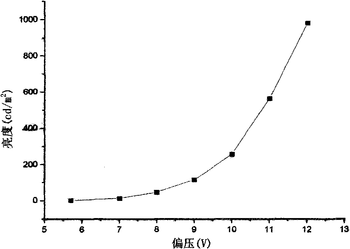
[0059] The voltage-brightness relationship of the light-emitting device in this example is as follows image 3 shown. It can be seen from the figure that if the metal film of the composite anode is replaced by silver, the 2 When the voltage was only 7.6 volts, this example compared the light-emitting devices made of graphene anodes provided by foreign journals ACSNANO 4(1)43-48 2010 and APPLIED PHYSICSLETTERS 96, 133301 2010, with lower voltage and higher power consumptio...

Embodiment 3

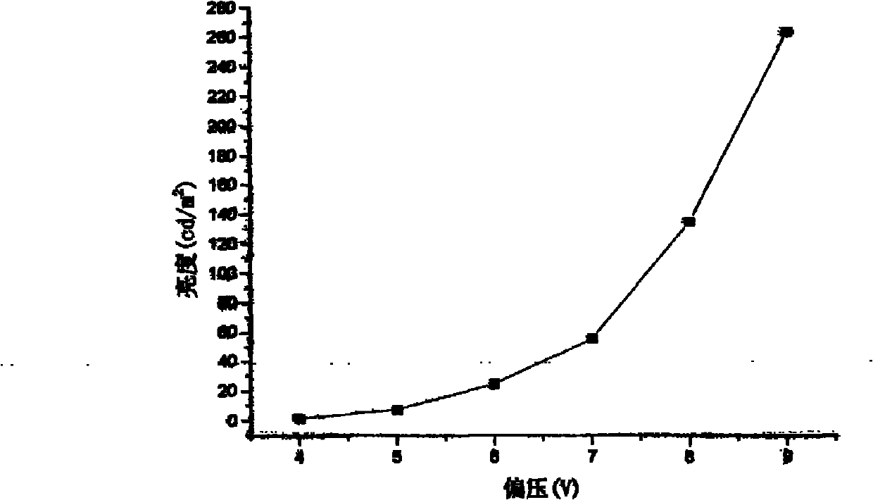
[0061] This example still adopts the multi-layer structure given in Example 1, and the substrate is made of PET (polyethylene terephthalate) plastic film, which is directly rinsed with ethanol and dried. The metal layer of the composite anode is made of aluminum and calcium mixed metal (mole percent ratio Al:Ca=90:10), and the P-type discoid organic compound layer is made of HATB and molybdenum oxide (MoO 3 ) blending (mol% ratio HATB: MoO 3 =70:30), other layer materials are the same as in Example 1. The deposition rate was kept at 3 angstroms / s for organic materials, 1 angstroms / s for LiF and molybdenum oxide, and 5 angstroms / s for aluminum, and the finally formed device structure was as follows:

[0062] PET / Al90%+Ca10%(15nm) / HATB70%+Molybdenum oxide 30%(40nm) / NPD(50nm) /

[0063] QUR 3 (50nm) / LiF(0.5nm) / Al(100nm)

[0064] The voltage-brightness relationship curve of the light-emitting device in this example is as follows Figure 4 shown.

[0065] This example compares...


PUM


Abstract

The invention relates to an organic electroluminescent device taking metal and P-type disc-shaped compound as composite anode, having a multi-layer structure. The organic electroluminescent device taking metal and P-type disc-shaped compound as composite anode comprises an anode film and has the improvement that the anode film is formed by a metal film and a P-type disc-shaped compound film. The composite anode of the invention breaks through the design thought of an ITO anode, and integrates the good conductivity of the metal and good hole injection of the P-type disc-shaped compound to obtain a transparent anode with favorable performance and low cost; and experiments show that: when being used for manufacturing luminescent device, the composite anode has low work voltage and has the advantages of saving the electricity and prolonging the service life under the same brightness; moreover, the cost of the composite anode is a small percentage of the ITO electrode, thereby greatly reducing the material cost of the luminescent device. Therefore, the organic electroluminescent device taking metal and P-type disc-shaped compound as composite anode has performance and cost advantages and is a powerful challenge to the traditional ITO anode to be repalced.

Description

technical field [0001] The invention relates to an organic electroluminescent device, in particular to an organic electroluminescent device in which a metal and a P-type discotic compound are used as a composite anode. Background technique [0002] Organic electroluminescence device (referred to as OLED) is a self-luminous, high-brightness, full-color display light-emitting element, which has an attractive prospect in the field of flat panel display. OLED display devices generally consist of a multilayer structure, typically a transparent or translucent substrate, an anode, a hole transport layer, a light emitting layer, an electron transport layer and a cathode. At present, people have rich research results on hole transport layer, light emitting layer, electron transport layer and cathode materials, but the anode is still limited to the traditional ITO anode and it is difficult to make a breakthrough. ITO is a kind of N-type metal oxide semiconductor material, its scienti...

Claims


Application Information

Patent Timeline
IPC IPC(8): H01L51/50H01L51/52
Inventor 闵军辉徐宁宋书清
Owner 西安文景光电科技有限公司
Why Eureka
Try Eureka