
Method for producing directly reduced iron from coal

A reduction of iron, direct technology, applied in furnace types, furnaces, shaft furnaces, etc., can solve the problems of increased energy consumption, expensive PSA equipment, large floor space, etc., and achieve the effect of improving production efficiency

Active Publication Date: 2011-04-13
CISDI SHANGHAI ENG CO LTD +1
View PDF4 Cites 21 Cited by
  • Summary
  • Abstract
  • Description
  • Claims
  • Application Information

AI Technical Summary

Problems solved by technology

If pressure swing adsorption is used to remove CO 2 The technical route of post-recycling needs to cool down the furnace top gas, and then needs to absorb heat to raise the temperature when it enters the circulating gas circuit, so the energy consumption is increased. At the same time, the pressure swing adsorption device is expensive and occupies a large area

Method used


Image

  • Method for producing directly reduced iron from coal
  • Method for producing directly reduced iron from coal
  • Method for producing directly reduced iron from coal

Examples


Embodiment 1

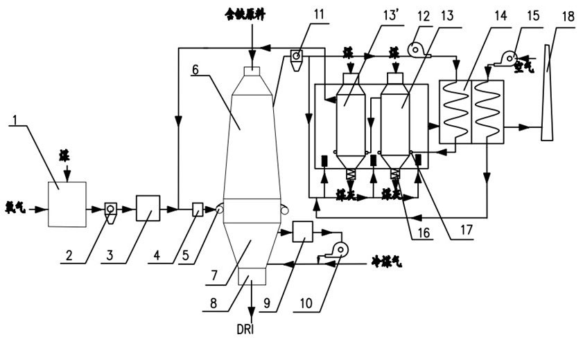
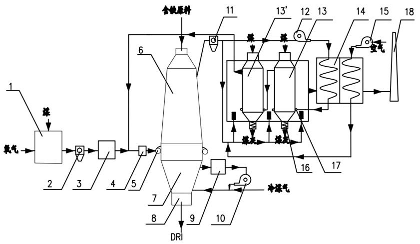
[0022] Example 1, such as figure 1 As shown, the mature oxygen-coal gas reaction device 1 is selected to produce reducing gas mainly composed of CO, and CO+H in the gas 2 The content meets the requirements of the shaft furnace for reducing gas, and after being dedusted by the first dust collector 2, it enters the surrounding pipe 5 of the reduction shaft furnace 6. Depending on the situation, a desulfurization device 3 and a heating device 4 can also be installed before the gas enters the surrounding pipe 5, so that the gas meets the system requirements. The reduction gas enters the reduction shaft furnace 6 uniformly along the circumference from the surrounding pipe 5 of the reduction shaft furnace 6 . Iron-containing raw materials are fed into the reduction shaft furnace 6 from the top, heated and reduced by the countercurrent high-temperature reducing gas to obtain hot DRI (direct reduced iron), and continue to descend to the cooling section 7 of the shaft furnace, and the...

Embodiment 2

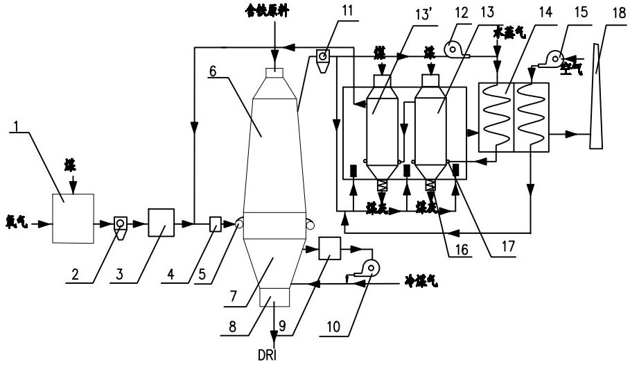
[0025] Example 2, such as figure 2 As shown, the difference between Example 2 and Example 1 is that the proportion of furnace top gas participating in gas upgrading is reduced, and water vapor is added before the gas to be upgraded enters the heat exchange device 14 to carry out hydrogen-rich upgrading of the gas.

[0026] The furnace top gas in the present invention does not need to be lowered in temperature, and can directly enter the carbon-based packed bed for reformation, reducing energy consumption. The fuel in the whole process is coal, and the exhaust of the system is CO 2 Gas, making full use of the energy of coal, reaches the lowest value of unit consumption.


PUM


Abstract

The invention discloses a method for producing directly reduced iron from coal. A technical process that CO is taken as main reducing gas for producing the directly reduced iron is adopted. The reducing gas is led into a reducing vertical furnace to carry out the reducing reaction with iron-containing raw materials to generate the directly reduced iron, much CO2 in the furnace top gas discharged from the reducing vertical furnace is modified into CO by adopting the reducing reaction, the CO is mixed with the reducing gas, and then, the mixed gas enters the reducing vertical furnace for reacting. In the invention, a carbon-based packed bed is used for modifying the top gas of the reducing vertical furnace, the modified gas component can meet the requirements of the reducing vertical furnace for the reducing gas, the fuel of the process route is coal, the CO2 gas is discharged by the system, and the coal energy can be fully used, thereby achieving a theoretical minimum value of unit consumption. Moreover, by using the carbon-based packed bed for modifying the gas, hydrogen can be enriched in the reducing gas by a method of adding steam, thereby improving the production efficiency.

Description

technical field [0001] The present invention relates to a method for producing reduced iron. Background technique [0002] Direct reduction ironmaking is a production process that uses coal, gas or liquid fuel as energy and a reducing agent to obtain solid direct reduced iron by reducing iron oxide in iron ore below the softening temperature of iron ore without melting. At present, the direct reduction production processes put into large-scale industrial application mainly include shaft furnace method, fluidization method, rotary kiln method and reaction tank method, among which the shaft furnace method is the main production process. In 2007, the world's shaft furnace production The direct reduced iron accounts for about 77.6%, and the typical representatives are the Midrex method and the HYL / Energiron method. Most of the world's shaft furnace production of direct reduced iron uses natural gas as raw material, and after catalytic cracking, high-temperature reducing gas is...

Claims


Application Information

Patent Timeline
IPC IPC(8): C21B13/02
Inventor 金明芳吕遐平罗凯张涛杨若仪董会国倪晓明宋华
Owner CISDI SHANGHAI ENG CO LTD
Learn More