System and method for power generating by jointly recovering waste heat of flue gas of sintering machine and exhaust gas of cooling machine

A power generation system and flue gas waste heat technology, which is applied in waste heat treatment, machines/engines, mechanical equipment, etc., can solve the problems of less than 30% waste heat recovery and utilization rate in sintering process, low overall efficiency of waste heat recovery and utilization, and low steam parameters, etc. Achieve the effects of improving waste heat recovery and utilization efficiency, increasing power generation efficiency, and increasing inlet temperature

Active Publication Date: 2011-04-13
NANJING KESEN KENEN ENVIRONMENT & ENERGY
View PDF6 Cites 35 Cited by
  • Summary
  • Abstract
  • Description
  • Claims
  • Application Information

AI Technical Summary

Problems solved by technology

According to relevant statistical data, the waste heat recovery utilization rate of my country's sintering process is still less than 30%. In addition, the average energy consumption of the sintering process of key iron and steel enterprises in my country is 64.83kgce / t, which is 7.2% higher than the advanced level in foreign countries. quite big
The temperature of the exhaust gas discharged from the single-pressure waste heat boiler is above 150°C, and the parameters of the steam generated by the heat pipe waste heat boiler are low, resulting in a low overall efficiency of waste heat recovery and utilization. This method cannot fully and reasonably recover and utilize the waste heat in the sintering process

Method used


Image

  • System and method for power generating by jointly recovering waste heat of flue gas of sintering machine and exhaust gas of cooling machine
  • System and method for power generating by jointly recovering waste heat of flue gas of sintering machine and exhaust gas of cooling machine
  • System and method for power generating by jointly recovering waste heat of flue gas of sintering machine and exhaust gas of cooling machine

Examples


Embodiment Construction

[0015] Further description will be made below in conjunction with drawings and embodiments.

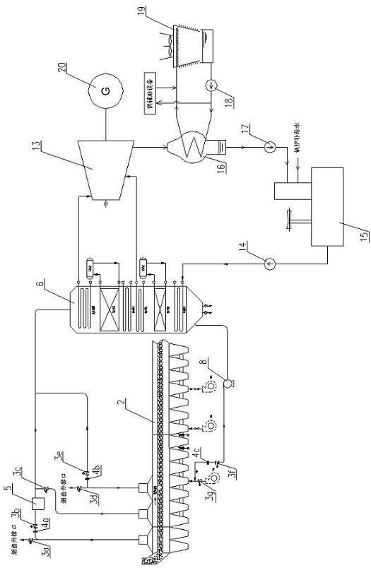
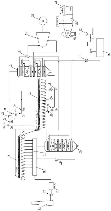
[0016] Such as figure 2 As shown, the combined recovery power generation system of sintering machine flue gas and cooler exhaust gas waste heat of the present invention uses a main waste heat boiler 9 to recover the waste heat of the flue gas at the high temperature section of the sintering machine 1 tail, and the flue gas inlet of the main waste heat boiler 9 is connected to the sintering machine 1. The large flue 12 in the high-temperature section at the rear is connected by air pipes. After heat exchange and cooling in the main waste heat boiler 9, the high-temperature flue gas is sent to the sintering machine by an induced draft fan 10. 1. The large flue 12 in the low-temperature section at the front. The outlet of 12 is connected with the inlet of the electrostatic precipitator 21 , the inlet of the main exhaust fan 22 is connected with the outlet of the electrostatic precipitat...


PUM


Abstract

The invention discloses a system and method for power generating by jointly recovering the waste heat of a flue gas of a sintering machine and an exhaust gas of a cooling machine, belonging to the technical field of power generation by using waste sintering heat of a steel and iron plant. The power generating system comprises a sintering machine flue gas waste heat utilizing system, a cooling machine exhaust gas waste heat utilizing system, a turbine generating system and a relevant auxiliary system, wherein a main waste heat discharging boiler is utilized to recover the waste heat of the flue gas of a high-temperature segment of the tail part of the sintering machine; a cooling machine waste heat boiler is utilized to recover the waste heat of the high-temperature exhaust gas of the cooling machine; and a high-temperature electric butterfly valve is arranged between the high-temperature segment and a low-temperature segment of a large flue positioned on the tail part of the sintering machine to prevent the wind pickup temperature of the flue gas from being reduced because a low-temperature flue gas and a high-temperature flue gas are directly mixed so as to ensure the high-temperature flue gas to enter the main waste heat discharging boiler for waste heat recovery. The system and method effectively utilizes the waste heat resources of the high-temperature flue gas of the machine tail of the sintering machine and a hot gas of the high-temperature segment of the cooling machine, enhances the waste heat recovery and utilization efficiency of a sintering process and increases the power generation capacity of the waste heat power generating system.

Description

technical field [0001] The invention relates to a power generation system and method for combined recovery of sintering machine flue gas and cooler waste gas waste heat, and belongs to the technical field of sintering waste heat power generation in iron and steel plants. Background technique [0002] According to the literature, the ironmaking system accounts for 69.41% of the total energy consumption of iron and steel production, and the energy consumption of the sintering process accounts for about 9-12% of the total energy consumption of the entire iron and steel enterprise, second only to the ironmaking process. The waste heat resources of the sintering process mainly have two parts: 1) Sensible heat of sintering ore accounts for about 45% of the total heat brought in during the sintering process, and the exhaust gas temperature in the high-temperature section of the cooler is about 350-420°C; 2) It accounts for about 45% of the total heat brought in. 24% of the sinterin...

Claims


Application Information

Patent Timeline
Patent Type & Authority Applications(China)
IPC IPC(8): F27D17/00F01K27/02F01K11/02F01D15/10
CPCY02P10/25Y02P80/15
Inventor 宋纪元何张陈侯宾才屠正瑞杨宏宜方明王静
Owner NANJING KESEN KENEN ENVIRONMENT & ENERGY
Why Eureka
Try Eureka