
Dynamical pressure type high-energy synthetic jet actuator

A synthetic jet and exciter technology, applied in the direction of electrical components, plasma, etc., can solve the problems of small jet flux and energy, low air pressure and density, and limited operating frequency of the exciter, so as to improve the operating frequency and Response speed, solving the effect of small jet flow rate and easy integration of control components

Inactive Publication Date: 2011-04-13
NAT UNIV OF DEFENSE TECH
View PDF5 Cites 24 Cited by
  • Summary
  • Abstract
  • Description
  • Claims
  • Application Information

AI Technical Summary

Problems solved by technology

[0003] 1. Small air volume, resulting in small momentum flux and energy of the jet, and weakened control ability;
[0004] 2. The natural cooling time of the inner cavity of the shell is long, which directly affects the recovery process of the inhalation and limits the operating frequency of the exciter. In addition, when the high frequency works, the residual ion concentration in the cavity is high to form a continuous discharge, which also limits the exciter. The working frequency, which leads to the recovery time is too long;
[0005] 3. The air pressure and density of the working environment are low, so that the air intake in the inner cavity of the shell is insufficient, and the jet flow cannot be formed effectively, resulting in the inability to work in a thin gas environment

Method used


Image

  • Dynamical pressure type high-energy synthetic jet actuator
  • Dynamical pressure type high-energy synthetic jet actuator
  • Dynamical pressure type high-energy synthetic jet actuator

Examples


Embodiment Construction

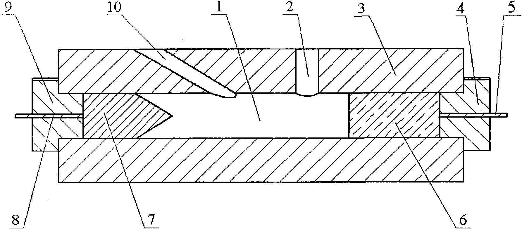
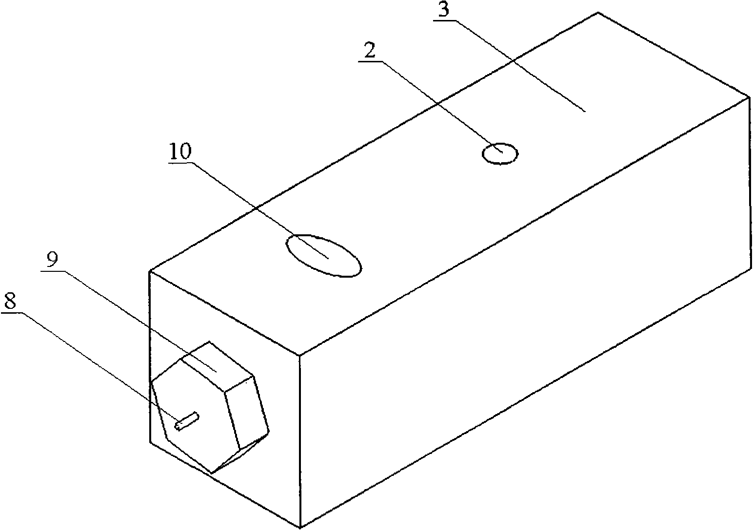
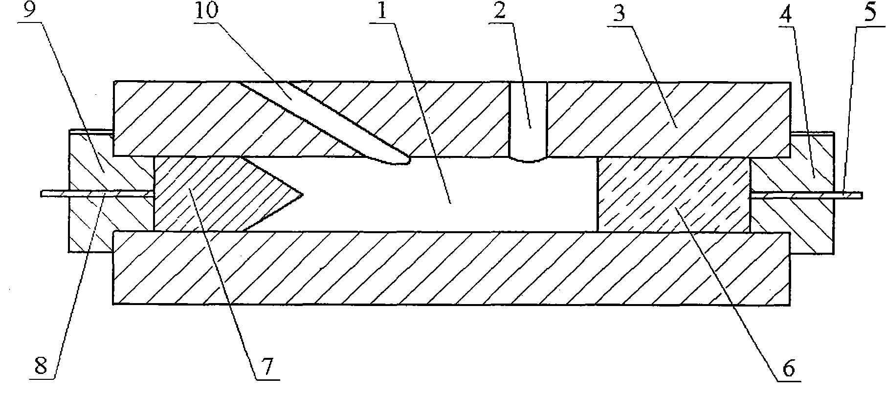
[0027] See attached Figure 1~2 , this embodiment of the dynamic pressure type high-energy synthetic jet exciter of the present invention, in order to accelerate the cooling rate of the housing, the material is made of glass-ceramic plate profiles with a thickness of 2mm, or with a large thermal conductivity. The casing 3 is made of a boron nitride plate profile with a thickness of 2mm. The housing 3 is in the shape of a cuboid with a size of 60×10×10mm 3 . Shell 3 as figure 1 As shown, a dynamic pressure inlet 10 and a jet outlet 2 are provided on both axial sides of its upper bottom surface. Among them, the dynamic pressure inlet 10, in order to increase the flow rate of the intake air flow, is made into a convex oval shape, which is opposite to the external high-speed incoming flow, so that the dynamic pressure of the incoming flow can be efficiently used to increase the flow rate that can be captured; while the jet outlet 2 is round hole shape, in order to increase the...


PUM


Abstract

The invention discloses a dynamical pressure type high-energy synthetic jet actuator, wherein a dynamic pressure inlet (10) and a jet outlet (2) are arranged on the bottom surface of a casing (3) of the dynamical pressure type high-energy synthetic jet actuator; an anode (6) and a cathode (7) are arranged in an inner cavity(1) of the casing (3); a first nut (4) which can be driven by a rotating belt to slide in the inner cavity (1) of the casing (3) is arranged on the anode (6); and a second nut (9) which can be driven by a rotating belt to slide in the inner cavity (1) of the casing (3) is arranged on the cathode (7). According to the actuator, the boosting can be realized by using a high-speed flowing ambient dynamic pressure, so that the synthetic jet flow, the work frequency and the response speed are greatly improved, the restore time is shortened and a fluid supply system and a valve can be avoided. The invention has the characteristics of simple structure, small size and low cost, controls elements to be integrated and is easy to produce in batch.

Description

technical field [0001] The invention relates to a high-energy jet flow / jet flow generator, in particular to a dynamic pressure type high-energy synthetic jet flow exciter which utilizes high-speed flow to quickly fill the excitation medium. Background technique [0002] The early high-energy synthetic jet actuator was a plasma synthetic jet actuator proposed by the Johns Hopkins University Applied Physics Laboratory in 2003. The actuator consists of a housing with an outlet and its anode and cathode. Its working cycle can be divided into three stages: the first stage, depositing energy; the second stage, discharging jet; the third stage, inhalation recovery. The mass flux of the gas passing through the actuator outlet in one cycle is 0, but the momentum flux is not 0, and the formed synthetic jet has high-speed characteristics, which makes it possible to use the plasma synthetic jet actuator to control the high-speed flow medium. However, since the third stage, that is, th...

Claims


Application Information

Patent Timeline
Patent Type & Authority Applications(China)
IPC IPC(8): H05H1/30
Inventor 罗振兵王林夏智勋王登攀胡建新
Owner NAT UNIV OF DEFENSE TECH
Learn More