Structure, method of forming structure, method of laser processing, and method of discriminating between true and false objects

一种结构体、激光的技术,应用在激光焊接设备、金属加工设备、化学仪器和方法等方向,能够解决成本增加、成本升高、作业烦杂等问题,达到简化作业工序、抑制成本提高、提高吸收率的效果

Inactive Publication Date: 2011-04-13
TOYO SEIKAN KAISHA LTD
View PDF7 Cites 7 Cited by
  • Summary
  • Abstract
  • Description
  • Claims
  • Application Information

AI Technical Summary

Problems solved by technology

[0027] Thus, even if the technique described in Patent Document 1 is used for marking, various colors cannot be achieved.
[0028] In addition, the technology described in Patent Document 2 requires a new light absorber, which leads to an increase in cost.
[0029] In addition, since the process of dispersing or applying the light absorbing agent is increased, the work is complicated
[0030] Furthermore, if carbon black is used as a light absorber, the transparent workpiece will turn black, so it cannot be commercialized in a transparent state.
[0031] In addition, the technology described in Patent Document 3 requires advanced technology to change the relative position of the lens and the transparent body so that the focal point of the laser light coincides with the deepest part of the hole, so it is not practical.
[0032] And, since a light-absorbing solution is newly required, it leads to an increase in cost

Method used


Image

  • Structure, method of forming structure, method of laser processing, and method of discriminating between true and false objects
  • Structure, method of forming structure, method of laser processing, and method of discriminating between true and false objects
  • Structure, method of forming structure, method of laser processing, and method of discriminating between true and false objects

Examples


Embodiment 1

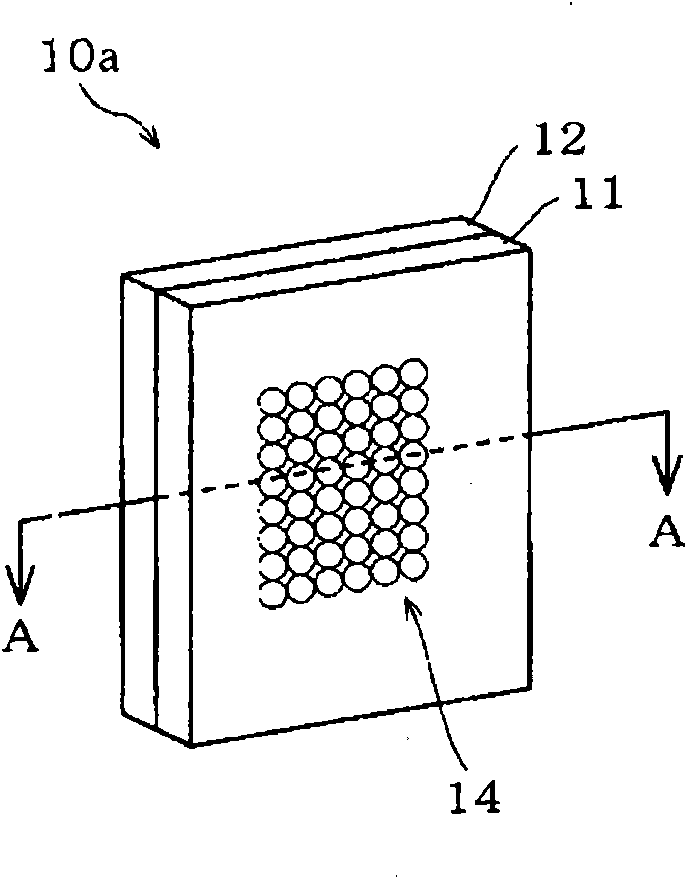
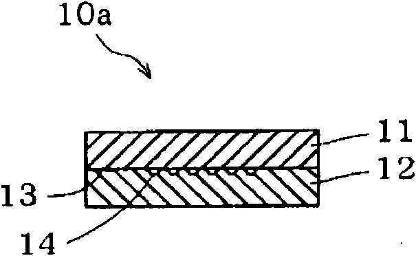
[0228] A plurality of stretched PET sheets having a thickness of 150 μm were prepared as the workpiece 10 d.

[0229] One or more of the stretched PET sheets were irradiated with ultraviolet light from a mercury xenon lamp (Ushio Denki) for 10 minutes at a distance of 12 cm.

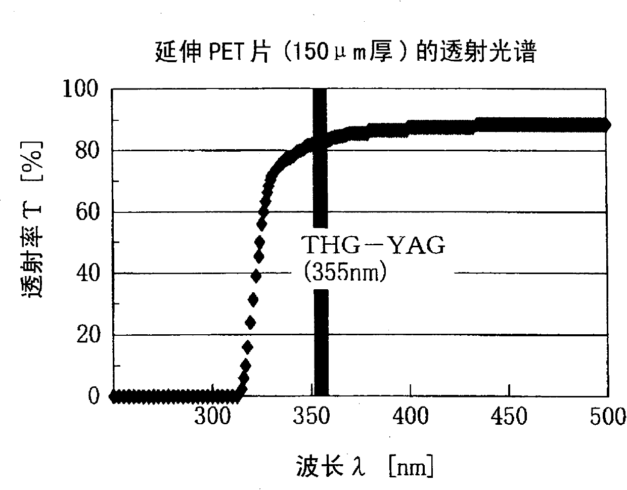
[0230] Here, as a result of measuring the transmittance of the stretched PET sheet with respect to a wavelength of 355 nm, it was 82.3% before irradiation and 76.7% after irradiation.

[0231] Next, the stretched PET sheet after UV irradiation and the unirradiated stretched PET sheet were prepared, and the Q-switched pulsed YAG laser third harmonic (wavelength 355 nm) exhibiting transmittance in the stretched PET sheet was irradiated with a laser irradiation device.

[0232] Here, the specifications of the pulsed YAG laser are a pulse width of 5 ns and a repetition rate of 10 Hz. In addition, the irradiation energy density is 400 [mJ / cm 2 ], one pulse is irradiated, and the irradiated energy density is...

Embodiment 2

[0238] A plurality of stretched PET sheets with a thickness of 150 μm were prepared as the workpiece 10 d.

[0239] One or more of these stretched PET sheets were irradiated with ultraviolet light emitted from a mercury xenon lamp (Ushio Denki) at a distance of 55 mm for 5 seconds.

[0240] Here, as a result of measuring the transmittance of the stretched PET sheet with respect to a wavelength of 355 nm, it was 82.3% before irradiation and 82.1% after irradiation.

[0241] Next, prepare the stretched PET sheet after UV irradiation and the stretched PET sheet that has not been irradiated, and irradiate the stretched PET sheet with the Q-switched pulsed YAG laser third harmonic that exhibits transmittance using an interference optical system (laser irradiation device 20). (wavelength 355nm).

[0242] Here, the specifications of the pulsed YAG laser are a pulse width of 5 ns and a repetition rate of 10 Hz. In addition, the irradiation energy density is 400 [mJ / cm 2 ] to emit a...

Embodiment 3

[0246] Four stretched PET sheets with a thickness of 150 μm were prepared as the workpiece 10 d.

[0247] One of these stretched PET sheets was irradiated with a UV lamp (black light) having an emission peak wavelength of 254 nm for 90 minutes. In addition, another sheet was irradiated with a 302 nm UV lamp for the same period of time. Furthermore, another sheet was irradiated with a 365 nm UV lamp for the same period of time. And, the UV lamp was not irradiated to the remaining stretched PET sheet.

[0248] Here, the transmittance of the stretched PET sheet with respect to a wavelength of 355nm was 82.3% without irradiation, 80.4% after irradiation at 254nm, 77.9% after irradiation at 302nm, and 81.8% after irradiation at 365nm.

[0249] Next, the above-mentioned four stretched PET sheets were irradiated with the third harmonic of YAG laser (wavelength: 355 nm) by a laser irradiation device.

[0250] Each PET sheet irradiated with UV of each peak wavelength was irradiated ...


PUM

PropertyMeasurementUnit
visible light transmittanceaaaaaaaaaa

Abstract

A multilayered structure in which laser marking is conducted in the second or a more inner layer without fail to prevent the marked part from being marred, fouled, falsified, or erased. The marking can be made in various colors. The structure (10) is a multilayer structure including an inner layer (12) and an outer layer (11). The inner layer (12) is formed from a resin which does not transmit light having a specific wavelength. The outer layer (11) is formed from a resin which transmits light having the specific wavelength. Recesses and protrusions (14) having a fine period have been formed by photodecomposition in at least part of that side of the surfaces (13) of the inner layer (12) which faces the outer layer (11).

Description

technical field [0001] The present invention relates to a structure as an object of laser processing, a structure forming method as a forming step of the structure, a laser processing method for performing predetermined processing by irradiating laser light, and a structure forming method or a laser processing method using the above The authenticity determination method of the present invention relates to, in particular, a marked structure by irradiation with laser light, a method for forming the structure, and a method for determination of authenticity. Background technique [0002] Laser marking refers to the method of implementing characters, symbols, markings, etc. on various industrial products by irradiating laser light. [0003] This laser marking is used in various fields due to its beauty, almost no deterioration, short processing time, and labor saving. [0004] However, laser marking is usually carried out on the surface of the product. Therefore, the appearance...

Claims


Application Information

Patent Timeline
Patent Type & Authority Applications(China)
IPC IPC(8): B23K26/00B23K26/067B32B7/02B32B27/00C08J7/00G07D7/12
CPCB23K26/06B23K26/4065B23K26/0084B29C2791/009B23K26/362B23K2203/16B23K2203/18B23K26/0057G07D7/124B32B27/36B32B27/16B23K26/53B23K26/355B23K2103/172B23K2103/18B23K2103/42B23K2103/50G07D7/003Y10T428/24628
Inventor 汤浅义之竹之内健黑田仁美平川叙夫细野宽子
Owner TOYO SEIKAN KAISHA LTD
Why Eureka
Try Eureka