Seawater desalination system

A seawater and brine technology, applied in seawater treatment, general water supply saving, heating water/sewage treatment, etc., can solve the problems of high energy, low cost, environmental pollution, etc.

Inactive Publication Date: 2011-04-20
黄定盛 +2
View PDF0 Cites 8 Cited by
  • Summary
  • Abstract
  • Description
  • Claims
  • Application Information

AI Technical Summary

Problems solved by technology

[0003] Most of the existing seawater desalination uses the principle of distillation to obtain fresh water. Its structure is simple, and the amount of water produced for desalination is large, but the energy consumption and pollution are also relatively large. It is mainly burned by an incinerator to heat the seawater to the boiling point and vaporize it. The produced water vapor is guided to a condensation chamber through a steam pipe, and fresh water is condensed through the condensation chamber. The fuel required by the incinerator is heavy oil, which causes great pollution to the environment after burning; in addition, a large amount of Seawater is heated from normal temperature to boiling point in order to generate water vapor, so it requires a lot of energy; there is also a seawater desalination device based on electric energy, which uses a large amount of electric energy to heat seawater to boiling point to vaporize, and obtain fresh water through condensation, so It also requires a lot of energy
[0004] Due to the rising awareness of environmental protection, coupled with the shortage of coal and oil and the difficulty of mining, the use of electric energy continues to increase, so we often face the crisis of power outages and power outages, and also face the crisis of producing a large amount of carbon dioxide due to heat emissions. Although kinetic energy generation devices using solar and wind power have been developed, the cost of the equipment is extremely expensive, and is affected by natural uncertain factors such as terrain, weather, sunlight angle, wind direction, etc., resulting in poor stability in obtaining kinetic energy , the cost is not low, so it is necessary to study and improve it.

Method used


Image

  • Seawater desalination system
  • Seawater desalination system
  • Seawater desalination system

Examples


Embodiment Construction

[0030] The structure, features and embodiments of the present invention are described below by illustrations, so that the present invention can be further understood.

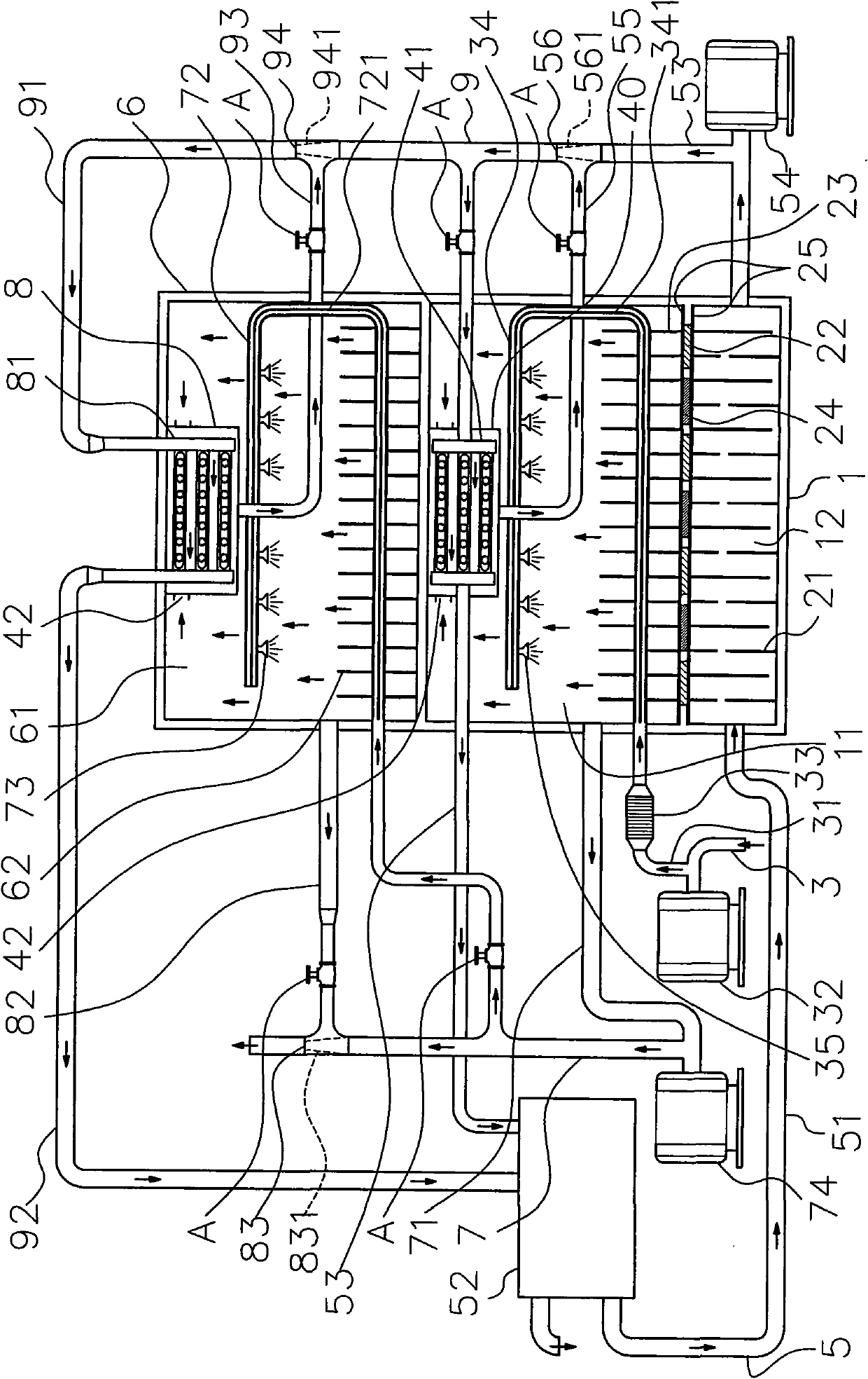
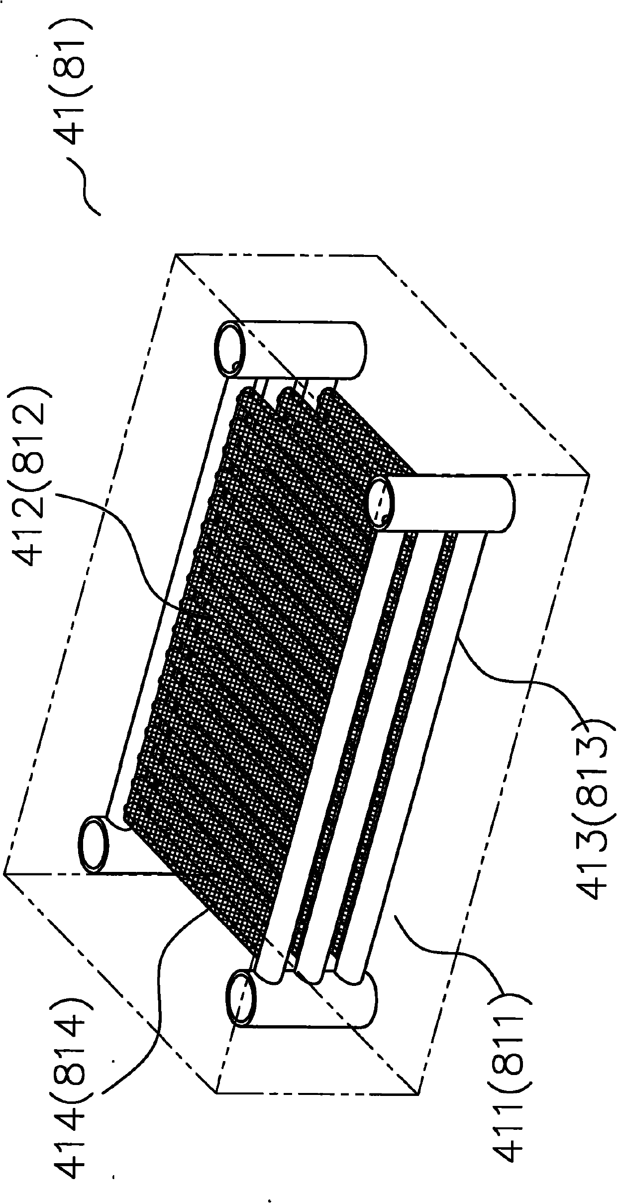
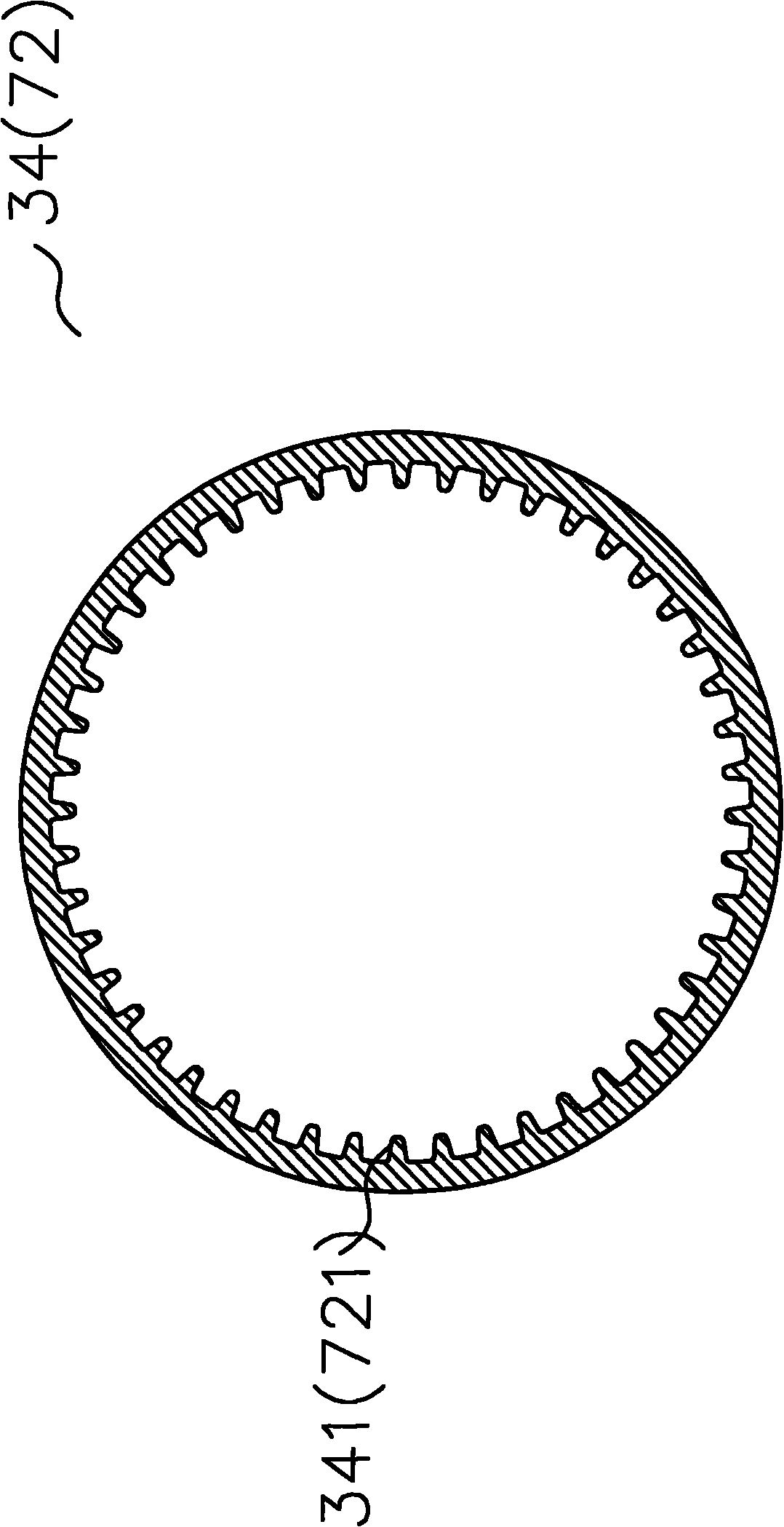
[0031] see figure 1 shown, with Figure 4 , Figure 5 and Image 6 As shown, a seawater desalination system includes an evaporation mechanism 2 and a condensation mechanism 4 communicated with the evaporation mechanism 2, wherein:

[0032] The evaporation mechanism 2 includes two conductors 25 arranged at intervals, and the intervals between the two conductors 25 are alternately provided with thermoelectric cooling chips 22 and thermoelectric power generation chips 24 at intervals. The thermoelectric cooling chips 22 have a cold surface and a hot surface. , and the cold and hot surfaces of the thermoelectric cooling chip 22 and the top and bottom surfaces of the thermoelectric power generation chip 24 are respectively attached to the two conductors 25, and the temperature generated by the cold and hot surfac...


PUM


Abstract

The present invention relates to a seawater desalination system, comprising: an evaporation mechanism and a condensation mechanism communicated with the evaporation mechanism. The evaporation mechanism comprises two conductors spaced at intervals, spaced and side-by side thermoelectric cooling sheets and thermo power wafers being installed at the intervals of two conductors. Thermoelectric sheet has a cold face and a hot face, which combined with the top and bottom faces of the thermo power chip is fitted in with the two conductors. The temperature induced by the cold face and the hot face of the thermoelectric cooling sheets is transmitted to thermo power chip. By temperature difference of thermoelectric cooling sheets, current is generated by the thermo power chip. The thermo power chip is connected to a condenser which transmits and stores the current to provide the thermoelectric cooling sheets with current. The invention generates regeneration energy and reduces heat discharging capacity by the temperature difference of thermoelectric cooling sheets in the process of seawater desalination.

Description

technical field [0001] The present invention relates to a seawater desalination system, in particular to a structure for generating renewable energy during the desalination process. Background technique [0002] Due to the large increase in population and the improvement of life, the demand for fresh water is constantly increasing. On the one hand, the impact of the greenhouse effect on the earth is becoming more and more significant, so human beings are already facing the problem of fresh water supply. Desalination of seawater is an effective way to solve the problem of freshwater supply. Since 70% of the earth is covered by seawater, the supply of seawater is inexhaustible for human beings. [0003] Most of the existing seawater desalination uses the principle of distillation to obtain fresh water. Its structure is simple, and the amount of water produced for desalination is large, but the energy consumption and pollution are also relatively large. It is mainly burned by ...

Claims


Application Information

Patent Timeline
Patent Type & Authority Applications(China)
IPC IPC(8): C02F1/04H02N11/00C02F103/08
CPCY02A20/124
Inventor 黄定盛邱英和张存财
Owner 黄定盛
Why Eureka
Try Eureka