

Intelligent oil well simulation experiment system and working method
An experimental system and intelligent technology, applied in earthwork drilling and production, wellbore/well components, etc., can solve the problems of no intelligent oilfield, etc., and achieve the effect of fast and convenient data collection and processing, simple operation and cost saving
- Summary
- Abstract
- Description
- Claims
- Application Information
AI Technical Summary
Problems solved by technology
Method used
Image

Examples
Embodiment 1
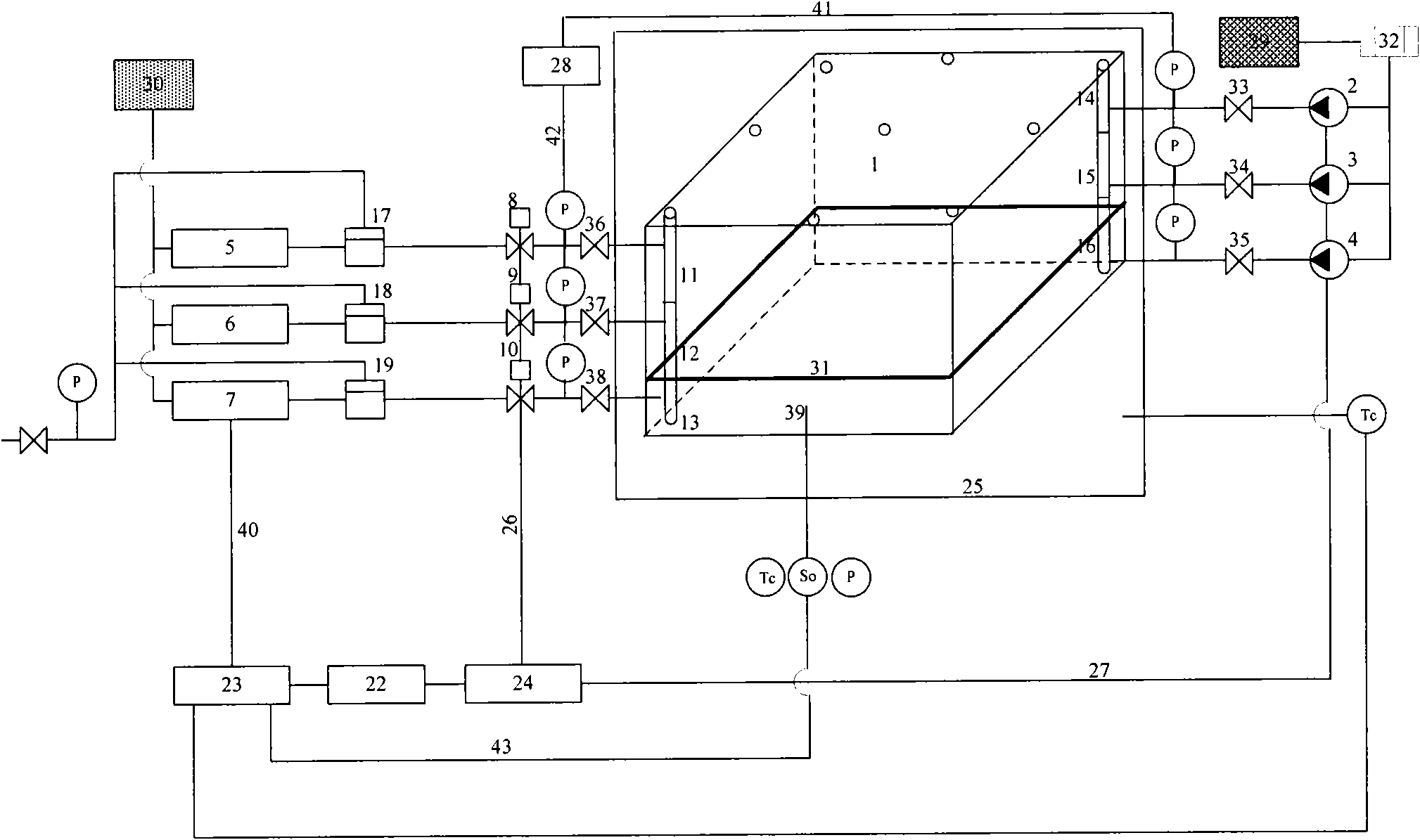
[0048] Example 1, such as Figure 1-3 Shown:
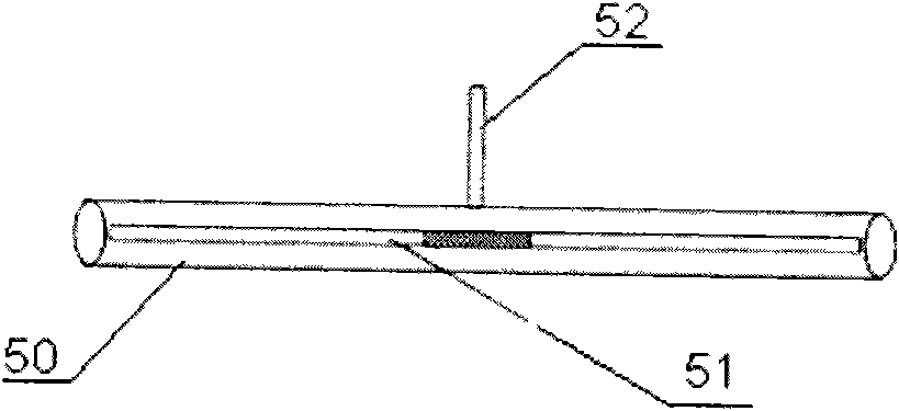
[0049] An intelligent oilfield simulation experiment system includes a three-dimensional heterogeneous reservoir simulation box 1, a simulated wellbore, a fluid injection module, a fluid production module, data acquisition modules 23, 28, an automatic control module 24, a constant temperature module 25, a saturation probe, Pressure sensor, temperature sensor and computer 22; figure 1 Middle Tc is a temperature sensor, So is a saturation probe, and P is a pressure sensor. The simulated wellbores are divided into injection simulated wellbores 14, 15, 16 and production simulated wellbores 11, 12, and 13;
[0050] The simulated wellbore is vertically arranged in a three-dimensional heterogeneous reservoir simulation box; the fluid injection module is connected to the injection simulated wellbores 14, 15, 16 through pipelines, and the fluid production module is connected to the production simulated wellbores 11, 12 through pipelines. , 13...
Embodiment 2
[0068] Embodiment 2. The working method of the experimental system as described in embodiment 1:
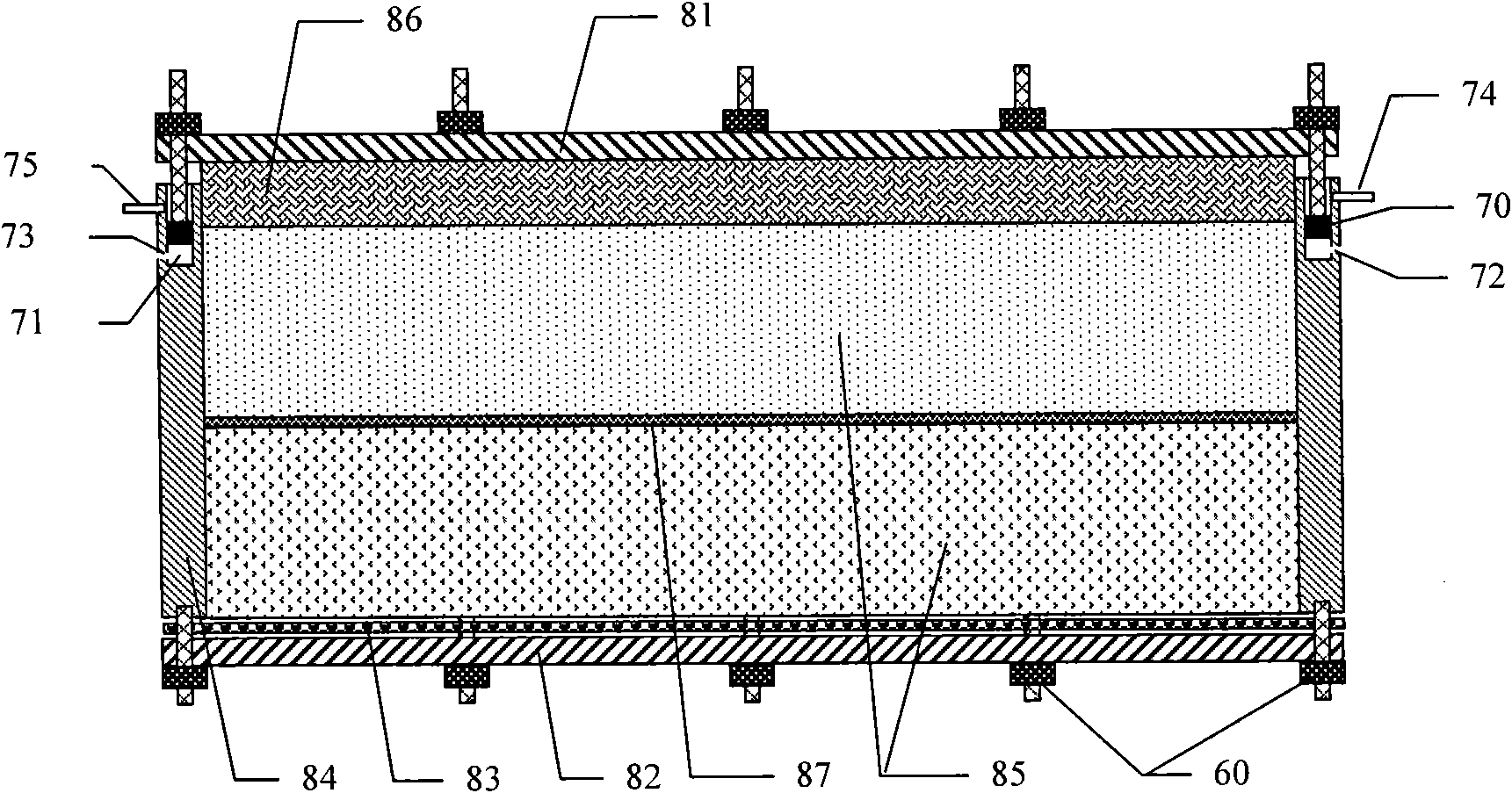
[0069] 1) Fill the sand 85 in the 3D heterogeneous reservoir simulation box 1. The sand filling position is between the bottom plate 82 and the large piston 86; the simulation wellbore, saturation probe, pressure sensor and temperature sensor are arranged; the large piston is covered 86. Connect the tank top cover 81, inject fluid into the three-dimensional heterogeneous reservoir simulation tank 1 through a manual pump, and compact the sand body in the model;
[0070] 2) Vacuum the 3D heterogeneous reservoir simulation box 1 through the simulated wellbore;
[0071] 3) Run the "intelligent oilfield data acquisition and control system" software installed in the computer 22, turn on the data acquisition module, and monitor the change of resistance value during the process of saturated water and oil;
[0072] 4) Record the volume of water used for saturation by simulating saturated water in...
Embodiment 3
[0078] The working method of Embodiment 3 is the same as that of Embodiment 2, the difference is:
[0079] The displacement fluid described in step 7) is gas, and the produced fluid is a mixture of oil, gas, and water.
PUM
 Abstract
Description
Claims
Application Information