Steam exhaust waste heat recovery unit
A waste heat recovery and exhausted steam technology, applied in steam engine installations, steam applications, mechanical equipment, etc., can solve the problems of low pressure and temperature, large volume flow, waste, etc., and achieve the effect of smooth flow
- Summary
- Abstract
- Description
- Claims
- Application Information
AI Technical Summary
Problems solved by technology
Method used
Image

Examples
Embodiment 1
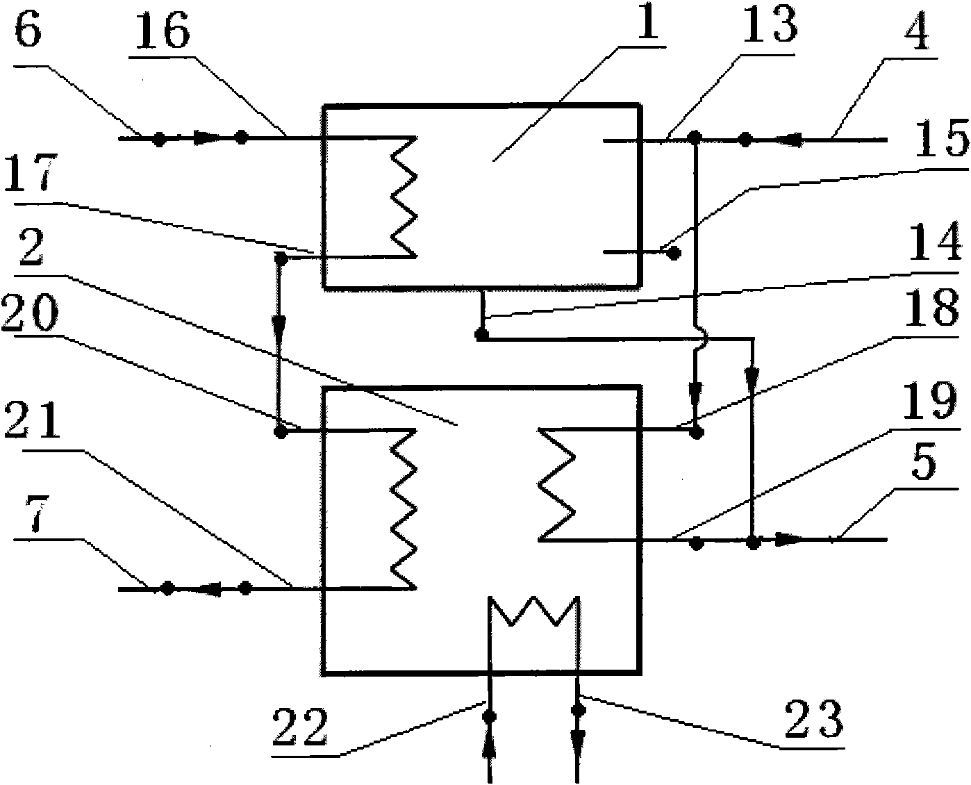
[0022] figure 1 It is a schematic diagram of the basic structure of the exhaust steam waste heat recovery unit in this embodiment. Such as figure 1 As shown, the exhaust steam pipe 4 of the low-temperature exhaust steam discharged by the steam turbine of the power plant or industrial production is connected with the inlet 13 of the exhaust steam side of the condenser and the inlet 18 of the exhaust steam side of the heat pump, and the condensate water outlet 14 of the condenser and the condensate water outlet 19 of the heat pump are connected with The return pipe 5 of the condensate recovery system is connected; the hot water side inlet 16 of the condenser is connected with the hot water inlet pipe 6, the hot water side outlet 17 of the condenser is connected with the hot water side inlet 20 of the heat pump, and the hot water side outlet 21 of the heat pump is connected with the The hot water outlet pipe 7 is connected; the heat pump high temperature heat source side inlet 2...
Embodiment 2
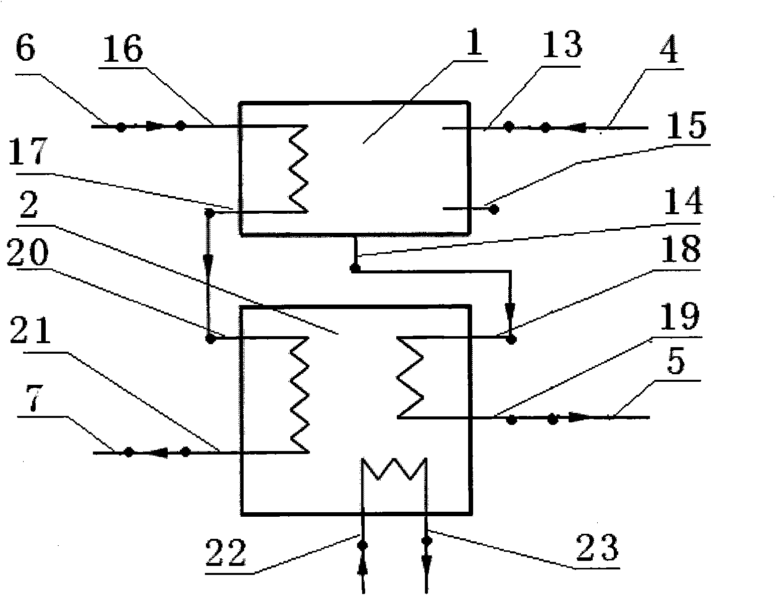
[0025] The structural representation of embodiment 2 is as figure 2 As shown, the exhaust steam side of the condenser 1 of the exhaust heat recovery unit and the absorption heat pump 2 are connected in series, that is, the exhaust pipe 4 of the low-temperature exhaust steam discharged from the steam turbine of the power plant or industrial production is connected with the inlet of the exhaust steam side of the condenser. 13 connection, the condenser condensate outlet 14 is connected to the exhaust steam side inlet 18 of the heat pump, the heat pump condensate outlet 19 is connected to the return pipe 5 of the condensate recovery system; the connection between the condenser 1 and the hot water side of the absorption heat pump 2 The method and the pipeline connection method of the high-temperature heat source side of the absorption heat pump 2 are the same as those in the first embodiment. The exhaust steam first enters the condenser and exchanges heat with the hot water. The h...
Embodiment 3
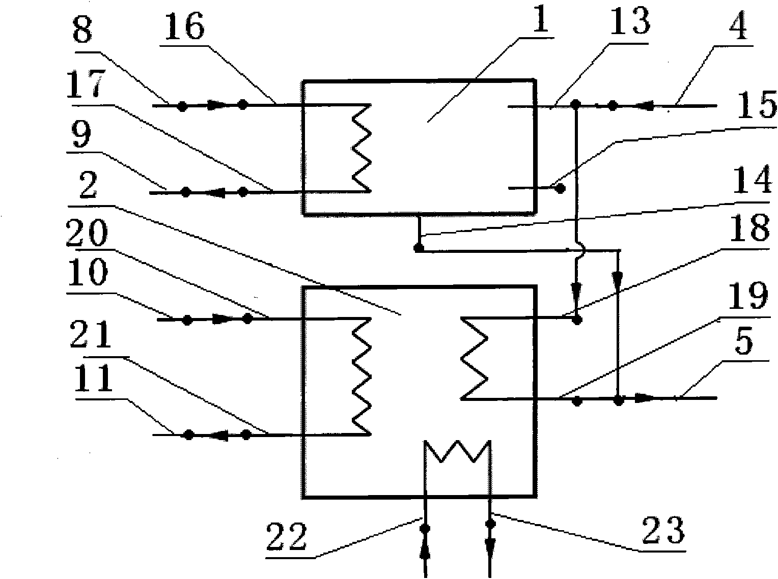
[0027] Embodiment 3 is a waste steam waste heat recovery unit that outputs high-temperature hot water and low-temperature hot water separately, such as image 3 As shown, the hot water side of the condenser 1 and the absorption heat pump 2 are respectively connected with the low-temperature heating system and the high-temperature heating system, the inlet 16 of the hot water side of the condenser is connected with the low-temperature heating water inlet pipe 8, and the heat of the condenser The water side outlet 17 is connected to the low temperature heating outlet pipe 9, the heat pump hot water side inlet 20 is connected to the high temperature heating water inlet pipe 10, the heat pump hot water side outlet 21 is connected to the high temperature heating outlet pipe 11, the condenser 1 and the absorption type The connection mode of the exhaust steam side of the heat pump 2 and the pipeline connection mode of the high-temperature heat source side of the absorption heat pump 2...
PUM
 Abstract
Description
Claims
Application Information
 - Generate Ideas
- Intellectual Property
- Life Sciences
- Materials
- Tech Scout
- Unparalleled Data Quality
- Higher Quality Content
- 60% Fewer Hallucinations
Browse by: Latest US Patents, China's latest patents, Technical Efficacy Thesaurus, Application Domain, Technology Topic, Popular Technical Reports.
© 2025 PatSnap. All rights reserved.Legal|Privacy policy|Modern Slavery Act Transparency Statement|Sitemap|About US| Contact US: help@patsnap.com