Eureka AIR delivers breakthrough ideas for toughest innovation challenges, trusted by R&D personnel around the world.

Improved high-efficiency unidirectional heat transfer pipe used for heat dissipation of microelectronics

A microelectronic and high-efficiency technology, applied in the field of heat pipes, can solve the problems of low condensation heat transfer coefficient, low heat transfer coefficient in the evaporation section, and no consideration of bead condensation, so as to improve the condensation heat transfer coefficient and reduce the viscous adhesion. Effect

Inactive Publication Date: 2012-10-31
BEIJING UNIV OF TECH
View PDF1 Cites 0 Cited by
  • Summary
  • Abstract
  • Description
  • Claims
  • Application Information

AI Technical Summary

Problems solved by technology

However, it does not consider that the liquid backflow caused by the viscous adhesion between the heat pipe working fluid and the inner wall inside the heat pipe is easy to cause the heat pipe working fluid to dry up, and the top of the condensation section is not easy to form beaded condensation because the surface is not treated. The problem of low coefficient and low heat transfer coefficient of the heating surface in the evaporation section

Method used


Image

  • Improved high-efficiency unidirectional heat transfer pipe used for heat dissipation of microelectronics
  • Improved high-efficiency unidirectional heat transfer pipe used for heat dissipation of microelectronics
  • Improved high-efficiency unidirectional heat transfer pipe used for heat dissipation of microelectronics

Examples


Embodiment Construction

[0017] Embodiments of the present invention are specifically described below in conjunction with the accompanying drawings:

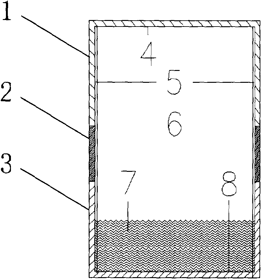
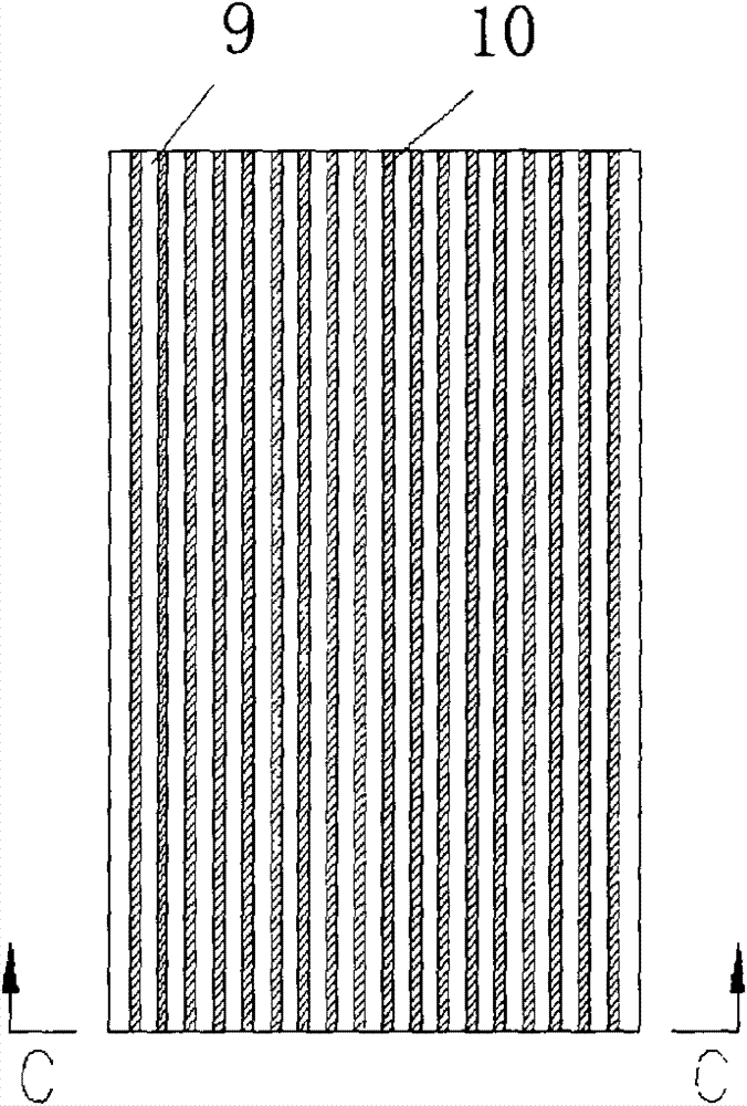
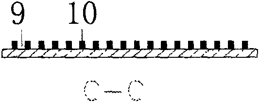
[0018] attached figure 1 It is a cross-sectional view of a heat pipe, including a condensation section 1, an adiabatic section 2, an evaporation section 3, a top of the condensation section 4, a capillary column channel 5, a closed vacuum chamber 6, a heat pipe working medium 7, and a scratched shallow groove surface 8. Among them, the condensing section 1 and the evaporating section 3 are made of materials with high thermal conductivity, such as copper, and the thermal conductivity is 394-401W / m K; the thermal insulation section 2 is made of materials with low thermal conductivity, such as steel, which has a thermal conductivity The coefficient is 36~54W / m·K; the three are seamlessly welded to form a whole; then the capillary channel 5 with channel structure is processed on the inner wall; the channel structure is as attached figure 2 , 3 As shown, ...


PUM


Abstract

The invention provides an improved high-efficiency unidirectional heat transfer pipe used for heat dissipation of microelectronics, belonging to the technical field of heat pipes, relating to a strictly unidirectional conductive gravity assisted heat pipe. The heat pipe of the invention is a seal chamber applied to the top of an heat dissipation object and is composed of a condensation section atthe upper part, a heat insulation section at the middle part and an evaporation section at the lower part, the interior of the heat pipe is filled with a working medium, and the heat pipe is characterized in that the bottom of the chamber is matched with the shape of the top of the heat dissipation object, and the inner surface is distributed with scratch shallow slots; the top of the chamber is subject to superhydrophobic surface treatment; the inner wall of the chamber is provided with vertically arranged groove channels and capillary column channels separated with rib channels and is subject to superhydrophobic surface treatment; gasification is easier to realize on the surface of the scratch shallow slots at the bottom; the capillary column channels make condensation working medium fluid rapidly reflux, thus avoiding that the working medium of the heat pipe is dried up; and the top of the condensation section is subject to superhydrophobic surface treatment, thus realizing dropwise condensation. Thus, the invention improves condensation heat exchange coefficient and enables the heat pipe to operate normally and stably.

Description

technical field [0001] The invention belongs to the technical field of heat pipes, and relates to a specific gravity heat pipe with strict unidirectional thermal conductivity. Background technique [0002] The application of microelectronic chips pervades all aspects of daily life, production and even national security, and plays an extremely important role in modern civilization. The trend of chip development is to further increase integration, reduce chip size and increase clock frequency. Taking computer chips as an example, the first chip produced by Intel in 1971 contained only 2,300 transistors, but now an Intel Pentium 4 chip integrates 42 million transistors. High integration is beneficial for upgrading the performance of electronic instruments and equipment. However, at the same time, the problems of chip energy consumption and heat dissipation have also emerged. With the rapid development of electronic technology, the high frequency and high speed of electronic ...

Claims


Application Information

Patent Timeline
Patent Type & Authority Patents(China)
IPC IPC(8): F28D15/02
Inventor 刘中良张广孟
Owner BEIJING UNIV OF TECH
Why Eureka
Eureka Blog
Learn More