Method for acquiring overall dynamics controlled quantity of independently driven-independent steering vehicle
An independent steering, independent driving technology, applied in the field of vehicle dynamics, can solve the problems of conservative vehicle dynamics control, conflict between vehicle dynamics control and system control capabilities, vehicle instability, etc., to improve rapidity and efficiency. Accuracy, ideal control, robustness-enhancing effects
- Summary
- Abstract
- Description
- Claims
- Application Information
AI Technical Summary
Problems solved by technology
Method used
Image

Examples
Embodiment Construction
[0031]The method for obtaining the vehicle dynamics control quantity of the independent drive-independent steering vehicle proposed in the present invention is described in detail in conjunction with the accompanying drawings and embodiments as follows:
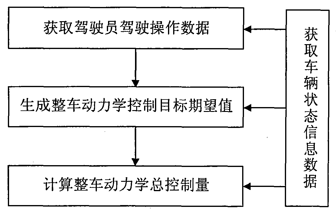
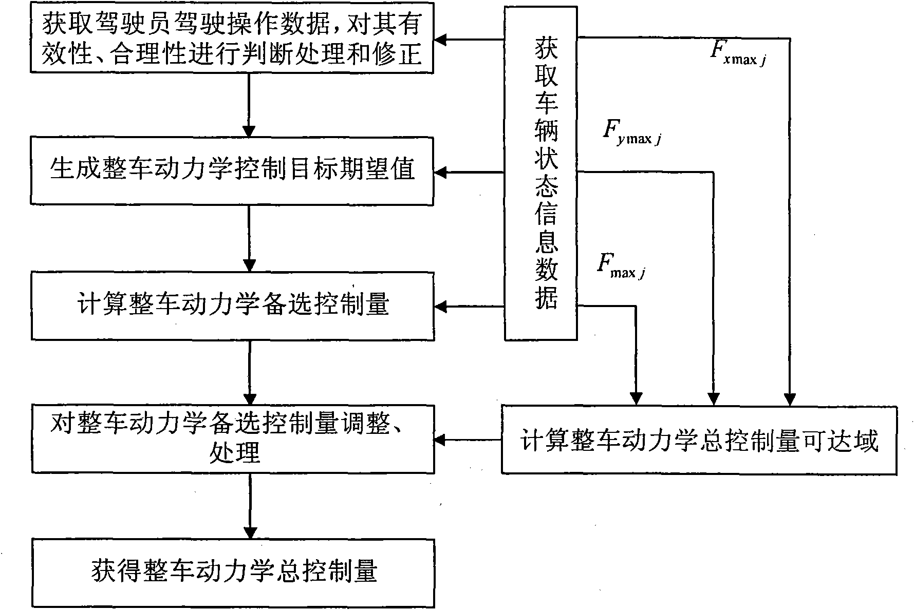
[0032] The AWID-AWIS vehicle vehicle dynamics control acquisition method of the present invention is as follows: figure 2 shown, including the following steps:
[0033] 1) Use the angle sensor to collect the expert data of the driving operation of the experienced driver, that is, the steering wheel angle δ P , accelerator pedal opening angle α a P , Brake pedal opening angle α b P , using wheel speed sensors, GPS (Global Positioning and Navigation System), and IMU (Inertial Measurement Unit) to collect the basic information of vehicle kinematics and dynamics corresponding to the driving operation data, and combine the information fusion method to obtain vehicle dynamics control information. The required vehicle state in...
PUM
 Abstract
Description
Claims
Application Information