Constant-tension winding machine for niobium titanium-copper superconducting solenoid coils

A solenoid coil, constant tension technology, applied in coil manufacturing, inductance/transformer/magnet manufacturing, electrical components, etc., can solve the problems of high labor intensity of operators, complicated winding process, and low utilization of equipment space. Achieve the effect of low labor intensity, simple winding process and compact space arrangement

Inactive Publication Date: 2011-04-27
HARBIN INST OF TECH
View PDF4 Cites 25 Cited by
  • Summary
  • Abstract
  • Description
  • Claims
  • Application Information

AI Technical Summary

Problems solved by technology

[0004] The purpose of the present invention is to solve the problems of complex winding process, high labor intensity of operators and low utilization rate of equipment space in existing superconducting solenoid coil winding machines, and to provide a niobium-titanium-copper superconductor Solenoid Coil Constant Tension Winding Machine

Method used


Image

  • Constant-tension winding machine for niobium titanium-copper superconducting solenoid coils
  • Constant-tension winding machine for niobium titanium-copper superconducting solenoid coils
  • Constant-tension winding machine for niobium titanium-copper superconducting solenoid coils

Examples


specific Embodiment approach 1

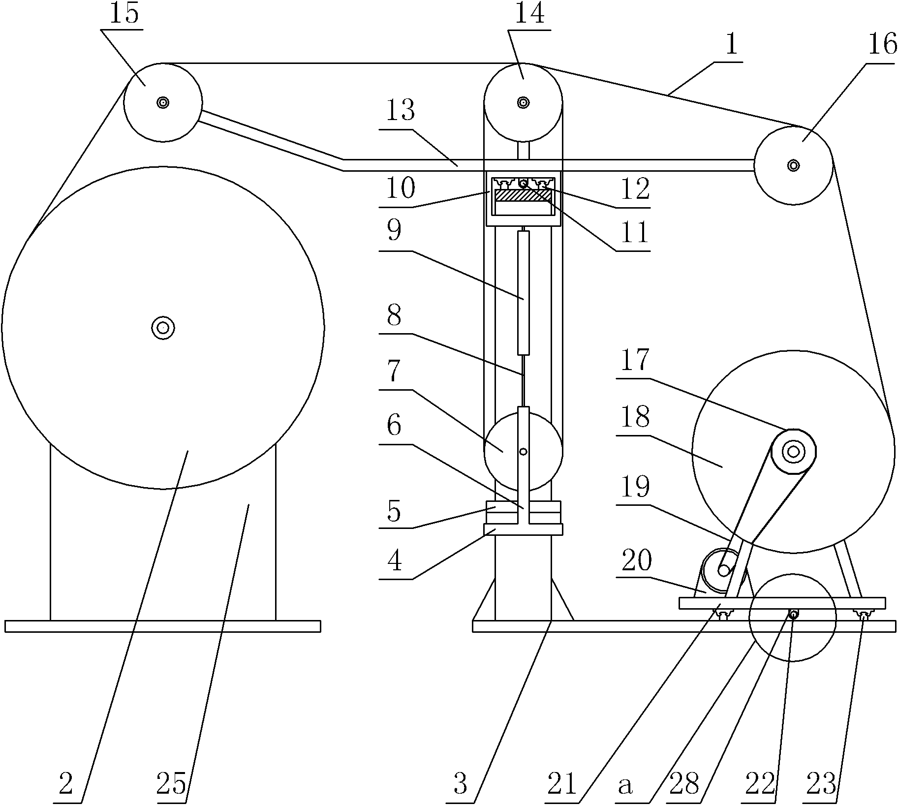
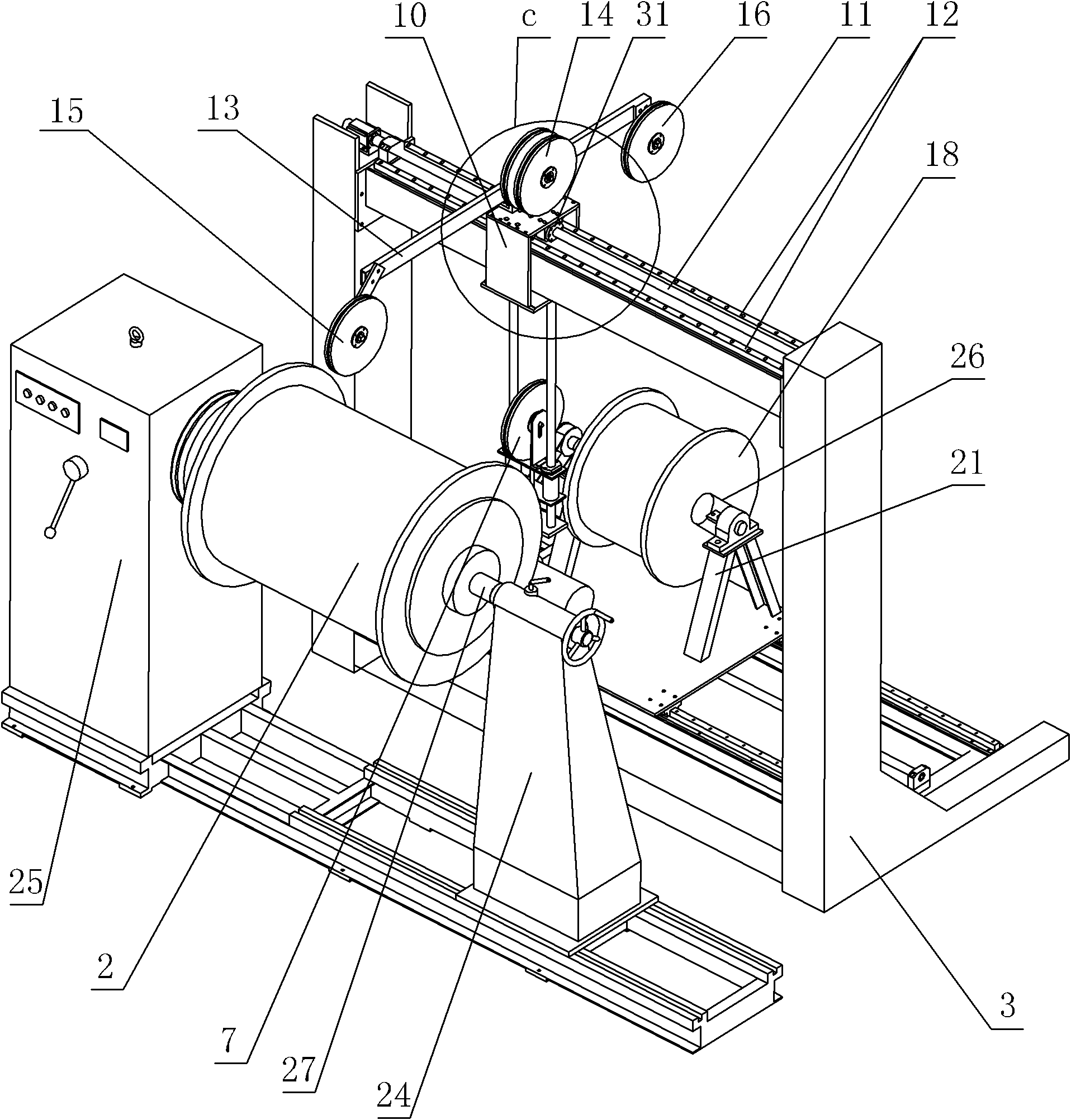
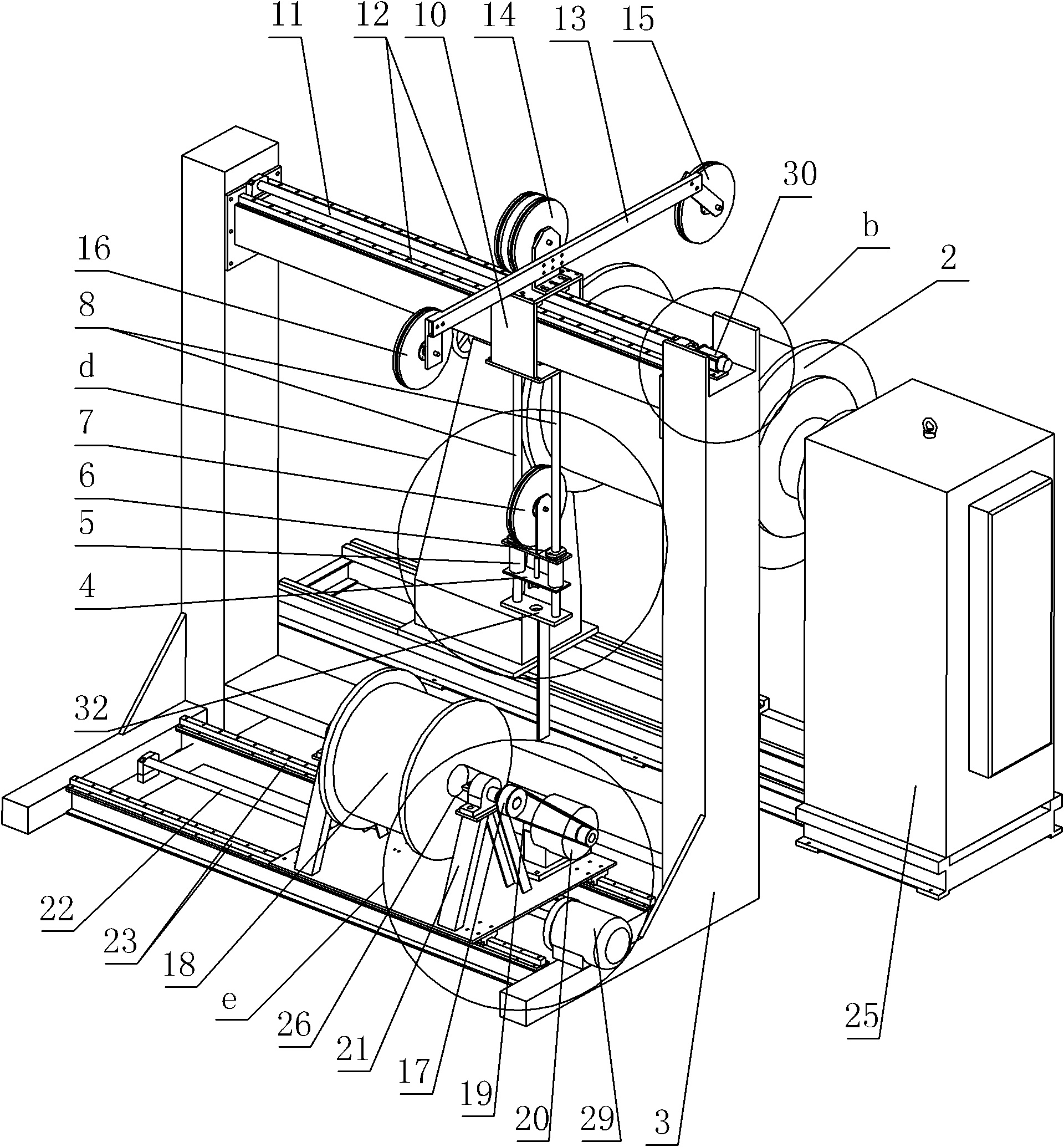
[0016] Specific implementation mode one: combine Figure 1-Figure 11 Describe this embodiment, the niobium-titanium-copper superconducting solenoid coil constant tension winding machine of this embodiment includes a superconducting solenoid coil 2 to be wound, an L-shaped gantry support 3, a counterweight plate 4, and a counterweight 5. Moving pulley axis support 6, moving pulley 7, linear displacement sensor 9, cable trolley 10, first ball screw 11, first drive motor 30, first sleeve 31, bracket 32, cable arm 13, double Track pulley 14, cable pulley 15, pay-off pulley 16, belt pulley 17, pay-off reel 18, transmission belt 19, reducer 20, pay-off bracket 21, second ball screw 22, winding bracket 24, winding Drive controller 25, first rotation shaft 26, second rotation shaft 27, second sleeve 28, second drive motor 29, two slide arms 8, two first slide block linear guides 12 and two second slides block linear guide 23;

[0017] The upper end face of the vertical part of the L...

specific Embodiment approach 2

[0022] Specific implementation mode two: combination image 3 The present embodiment will be described. The diameter of the movable pulley 7 in this embodiment is equal to the diameter of the double track pulley 14 , and the movable pulley 7 is located directly below the double track pulley 14 . Such arrangement facilitates coil winding. Other compositions and connections are the same as in the first embodiment.

specific Embodiment approach 3

[0023] Specific implementation mode three: combination image 3 The present embodiment will be described. The pay-off reel 18 of the present embodiment is located directly below the pay-off pulley 16 . Such arrangement facilitates coil winding. Other compositions and connections are the same as those in Embodiment 1 or Embodiment 2.


PUM


Abstract

The invention provides a constant-tension winding machine for niobium titanium-copper superconducting solenoid coils, relating to a winding machine for superconducting solenoid coils. The invention solves the problems of complex winding process, high labor intensity of operators and low use ratio of equipment space of the current winding machine for superconducting solenoid coils. In the invention, an L-shaped portal frame is provided with two first slider linear guide rails and a first ball screw, and a double-track pulley is installed on a wiring arm. A wiring support arm of the wiring arm is provided with a wiring pulley, and a wire loading support arm of the wiring arm is provided with a wire loading pulley. A movable pulley is installed on a movable pulley axis support, and a wire loading tray is rotatably installed on a wire loading support. A superconducting solenoid coil to be wound is rotatably installed on a winding support, and a lead wire is led out through the wire loading tray and wound on the superconducting solenoid coil to be wound after moving round the wire loading pulley, one slideway of the double-track pulley, the movable pulley, the other slideway of the double-track pulley and the wiring pulley. The constant-tension winding machine is suitable for winding niobium titanium-copper superconducting solenoid coils.

Description

technical field [0001] The invention relates to a superconducting solenoid coil winding machine, in particular to a niobium-titanium-copper superconducting solenoid coil constant tension winding machine, which belongs to the technical field of superconducting engineering. Background technique [0002] The operating temperature of the solenoid coil wound with niobium-titanium-copper superconducting wire is generally around 4.2K, so when this type of superconducting coil drops from normal temperature to the operating temperature, internal heat will be generated due to the different shrinkage rates of various materials inside the coil. The superconducting wire will bear increasing Lorentz force during the process from excitation to working current. When designing this type of superconducting coil, the thermal stress and Lorentz force generated in the above two processes of this type of superconducting coil are usually controlled by selecting the appropriate winding prestress so...

Claims


Application Information

Patent Timeline
Patent Type & Authority Applications(China)
IPC IPC(8): B65H54/02B65H59/00H01F41/06H01F41/094
Inventor 徐风雨刘孝坤陈安斌
Owner HARBIN INST OF TECH
Why Eureka
Try Eureka