Two-stage expansion piston air motor device

A pneumatic engine and two-stage expansion technology, applied in the field of power devices, can solve problems affecting the working efficiency of the system, achieve stable power output, improve energy use efficiency, and high energy transfer efficiency

Inactive Publication Date: 2011-04-27
NANJING UNIV OF SCI & TECH
View PDF5 Cites 15 Cited by
  • Summary
  • Abstract
  • Description
  • Claims
  • Application Information

AI Technical Summary

Problems solved by technology

Although they all use compressed gas to expand and do work, they still use a crank-slider mechanism in the transmission structure. The work is done when the chamber expands to push the piston, but it does not do work when the piston moves in reverse, and the crank acts on the cylinder. The lateral force does not work, which affects the working efficiency of the system

Method used


Image

  • Two-stage expansion piston air motor device
  • Two-stage expansion piston air motor device
  • Two-stage expansion piston air motor device

Examples


Embodiment Construction

[0011] The present invention will be described in further detail below in conjunction with the accompanying drawings.

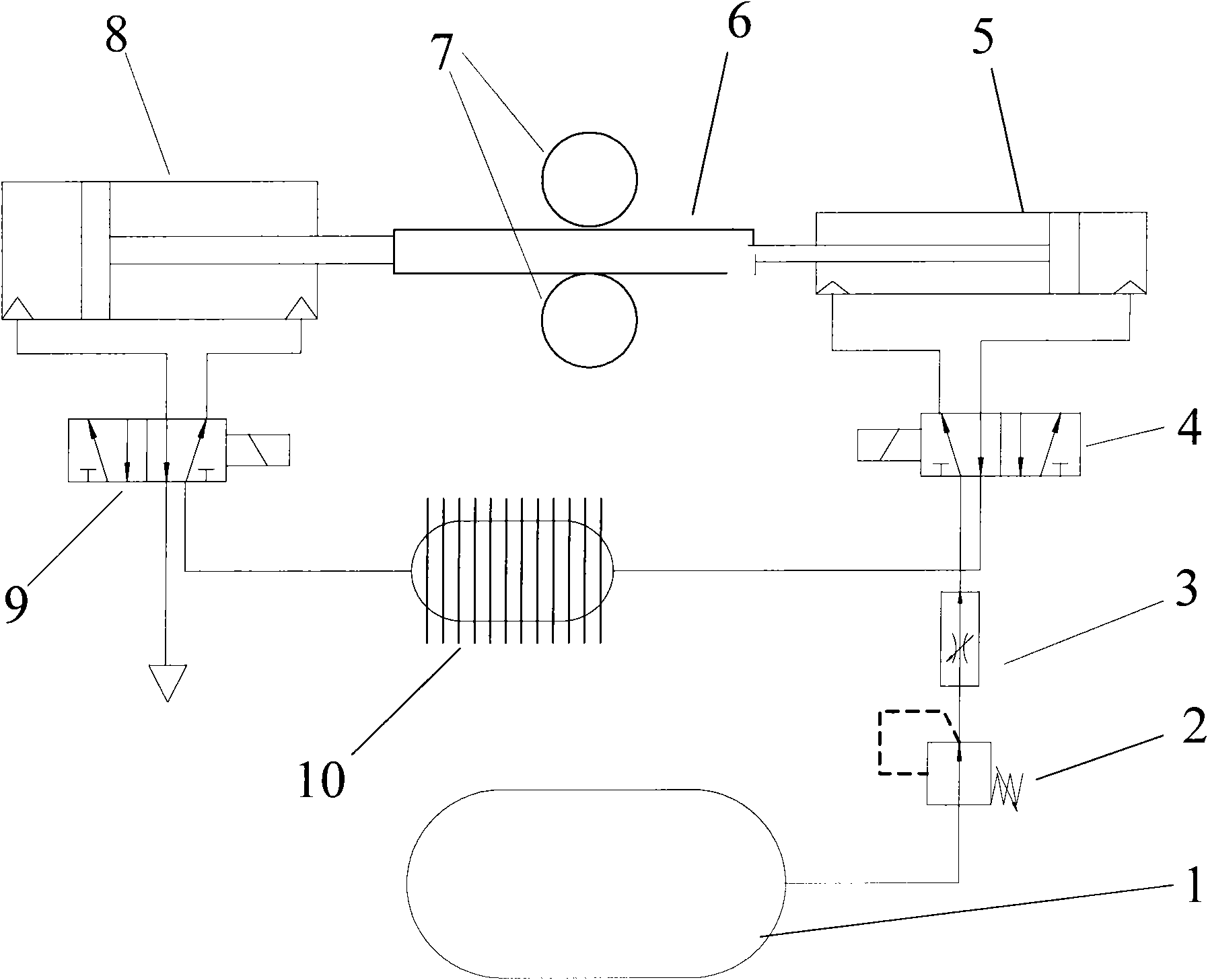
[0012] Such as figure 1 Shown is a schematic diagram of the air pressure control loop system of the present invention. Wherein comprise a gas tank 1, there is the compressed gas of 30Mpa in the gas tank, pressure reducing valve 2 is connected with 1 through flexible pipe, and its function is to reduce the compressed gas of 30Mpa to 1Mpa. After the throttle valve 3 is connected to the pressure reducing valve 2, the function of the throttle valve 3 is to adjust the flow rate of the gas. A valve port at the lower end of the first electromagnetic reversing valve 4 is connected to the throttle valve 3, and the other valve port is connected to the transition gas tank and the heat exchange system 10, and the effect of the 10 is to make the passing gas absorb the heat of the external environment. The two valve ports at the upper end of the 4 are connected to the fi...


PUM


Abstract

The invention discloses a two-stage expansion piston air motor device. A reducing valve is connected with an air tank through a hose; one end of a throttling valve is connected with the reducing valve, and the other end of the throttling valve is connected with a valve port at the lower end of an electromagnetic reversing valve; the other valve port is connected with a transition air tank and a heat exchange system; two valve ports at the upper end of the electromagnetic reversing valve are connected with a first-stage cylinder; a piston rod in the first-stage cylinder is connected with the right end of a rack; the left end of the rack is connected with a second-stage cylinder; an upper cylindrical gear is arranged above the rack, and a lower cylindrical gear is arranged below the rack; the rack forms two pairs of gear pairs with the upper gear and the lower gear; two valve ports at the upper end of the electromagnetic reversing valve are connected with two working cavities of the second-stage cylinder through hoses; and a valve port at the lower end of the electromagnetic reversing valve is connected with the transition air tank and the heat exchange system through hoses, and theother valve port is connected with the external environment through a hose. An automobile power device which takes compressed air as a power source can drive a vehicle to run instead of petroleum, diesel oil or liquefied petroleum gas fuel, so that real zero emission of tail gas of automobiles is realized.

Description

technical field [0001] The invention relates to a power device capable of driving a vehicle by using compressed air as a power source, in particular to a two-stage expansion piston type pneumatic engine device. Background technique [0002] According to statistics, the current global daily oil consumption is about 50 million barrels, of which about 50% is used for transportation, and about 80% of which is used for automobiles. At present, the proven oil reserves in the world can only be used for about 40 years based on the current oil consumption. Therefore, if petroleum is still used as the sole energy source for vehicle power, the automobile industry will soon come to an end. On the other hand, automobile exhaust has become the largest source of pollutants such as CO, NOx and CH in large cities in my country. The large amount of carbon dioxide gas emitted by burning is the main cause of the global warming effect. The incomplete combustion of automobile fuel has also bec...

Claims


Application Information

Patent Timeline
Patent Type & Authority Applications(China)
IPC IPC(8): F01B1/08F01B25/00F01B31/00
Inventor 潘孝斌谈乐斌顾辉
Owner NANJING UNIV OF SCI & TECH
Why Eureka
Try Eureka