Low-vibration energy-saving air distribution camshaft of engine of motor vehicle

A valve cam, engine technology, applied in the direction of machine/engine, engine components, mechanical equipment, etc., can solve the problems of large valve switch vibration, unstable crankshaft valve opening and closing process, high noise, etc., to reduce fuel consumption, valve spring Moderate tightness, reducing vibration effect

Inactive Publication Date: 2011-04-27
李云合
View PDF5 Cites 4 Cited by
  • Summary
  • Abstract
  • Description
  • Claims
  • Application Information

AI Technical Summary

Problems solved by technology

[0003] The purpose of the present invention is to provide a low-vibration and energy-saving gas distribution camshaft for motor vehicles, so as to solve the defects that the variable speed rotation of the crankshaft causes the valve opening and closing process to be unstable, which leads to large vibration and noise of the valve switch

Method used


Image

  • Low-vibration energy-saving air distribution camshaft of engine of motor vehicle
  • Low-vibration energy-saving air distribution camshaft of engine of motor vehicle
  • Low-vibration energy-saving air distribution camshaft of engine of motor vehicle

Examples


specific Embodiment approach 1

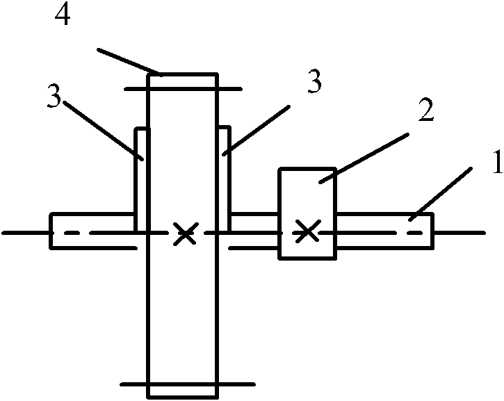
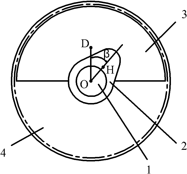
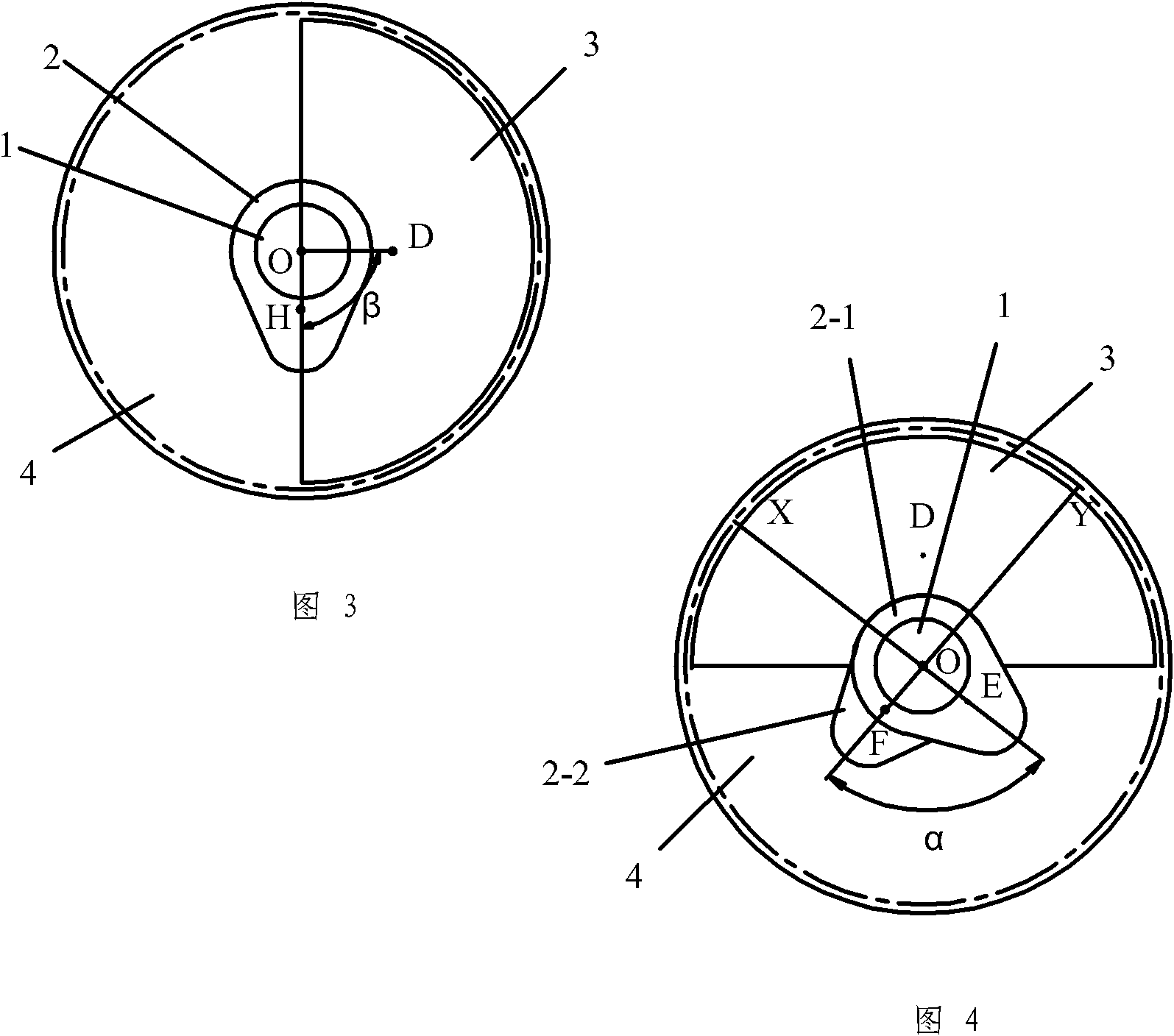
[0006] Specific embodiment one: the following combination figure 1 and figure 2 The present embodiment will be specifically described. This embodiment includes a shaft body 1, a valve cam 2 and a power transmission wheel 4. The valve cam 2 and the power transmission wheel 4 are fixed on the shaft body 1 and the former two rotate coaxially with the shaft body 1. It also includes Eccentric disc body 3, the eccentric disc body 3 is arranged on the shaft body 1 and the disc body surface of the eccentric disc body 3 is perpendicular to the shaft body 1, the mass center D of the eccentric disc body 3 in the circumferential direction of the shaft body 1 The connection line with the shaft body 1 is deviated from the connection line between the mass center H of the valve cam 2 and the shaft body 1 . The power transmission wheel 4 transmits the power from the crankshaft of the internal combustion engine.

specific Embodiment approach 2

[0007] Specific embodiment two: the following combination figure 1 and figure 2 The present embodiment will be specifically described. The difference between this embodiment and the first embodiment is that the eccentric disc body 3 is fixed on one end face of the power transmission wheel 4 . The eccentric disc body 3 of this embodiment is arranged on the shaft body 1 in this way, which not only achieves a compact structure, but also enables the eccentric disc body 3 to be reliably fixed.

specific Embodiment approach 3

[0008] Specific embodiment three: the following combination figure 1 The present embodiment will be specifically described. The difference between this embodiment and the second embodiment is that it further includes another eccentric disc body 3 , and the two eccentric disc bodies 3 are respectively fixed on both end faces of the power transmission wheel 4 .


PUM


Abstract

The invention discloses a low-vibration energy-saving air distribution camshaft of an engine of a motor vehicle, and relates to an air distribution camshaft of an internal combustion engine of a motor vehicle. The camshaft is used for the engine of the motor vehicle. The camshaft overcomes the defects of high air valve switching vibration and high noise caused by unsmooth entrance in the air valve switching process due to the variable acceleration rotation of a crankshaft. The camshaft comprises a shaft body, an air distribution cam and a power transmission wheel; the air distribution cam and the power transmission wheel are fixed on the shaft body and coaxially rotate with the shaft body; the camshaft also comprises an eccentric disc body; the eccentric disc body is arranged on the shaft body, and the surface of the eccentric disc body is vertical to the shaft body; and in the circumference direction of the shaft body, the connecting line of the mass center of the eccentric disc body and the shaft body deviates from the connecting line of the mass center of the air distribution cam and the shaft body. The tension of an air valve spring can be adjusted to be better moderate so as to facilitate the reduction of power consumption of the engine and achieve the effects of saving oil, balancing the impact force of the crankshaft, reducing the vibration of the engine and improving the output torque and power.

Description

technical field [0001] The invention relates to a valve camshaft of an internal combustion engine of a motor vehicle. Background technique [0002] like Figure 5 and Image 6 As shown, the conventional motor vehicle internal combustion engine relies on the cam 10 on the valve camshaft to periodically drive the distal end of the valve rocker arm to open the valve of the cylinder for air exchange. At the same time, the reaction force of the valve spring also acts on the valve rocker arm, so that the proximal end of the valve rocker arm tightly abuts on the cam 10 of the valve camshaft. The rotation power of the valve camshaft comes from the crankshaft 11 of the internal combustion engine cylinder. As we all know, the rotation of the crankshaft 11 is periodically variable acceleration, which is derived from the explosive stroke and the suction stroke when the power is performed between the engine cylinder and the piston 12. cyclical changes. The variable acceleration rotati...

Claims


Application Information

Patent Timeline
Patent Type & Authority Applications(China)
IPC IPC(8): F01L1/053
Inventor 李云合
Owner 李云合
Why Eureka
Try Eureka