Heat exchange tube for evaporator and evaporator formed by same

A technology for evaporators and heat exchange tubes, which is applied in the direction of evaporators/condensers, refrigeration components, tubular elements, etc., which can solve the problems of inability to solve the charging volume of refrigeration systems, complex system structures, and limited applications, and achieve omission of throttling The effect of step-down process, solving application limitations, and reducing filling volume

Inactive Publication Date: 2011-04-27
TIANJIN UNIV OF COMMERCE
View PDF4 Cites 13 Cited by
  • Summary
  • Abstract
  • Description
  • Claims
  • Application Information

AI Technical Summary

Problems solved by technology

However, since adding a circulating pump means more power consumption, the structure is more complicated
[0006] In the traditional form of vapor compression refrigeration cycle, the evaporation process of the refrigerant in the evaporator must be ensured in a low-pressure environment, so the high-pressure refrigerant after compression and condensation needs to go through a throttling and decompression process before entering the evaporator. The system structure complex
[0007] Among the above-mentioned various forms of evaporators, although each has its own characteristics, most of them cannot solve the problem of the charging volume of the refrigeration system.
Especially for flammable and explosive refrigerants, there are strict regulations on the charging amount of refrigerants in practical applications, which greatly limits the application of these refrigerants in some large-scale refrigeration systems

Method used


Image

  • Heat exchange tube for evaporator and evaporator formed by same
  • Heat exchange tube for evaporator and evaporator formed by same
  • Heat exchange tube for evaporator and evaporator formed by same

Examples


Embodiment Construction

[0027] The present invention will be described in detail below in conjunction with the accompanying drawings and specific embodiments.

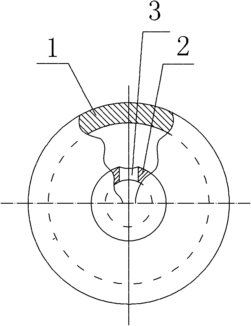
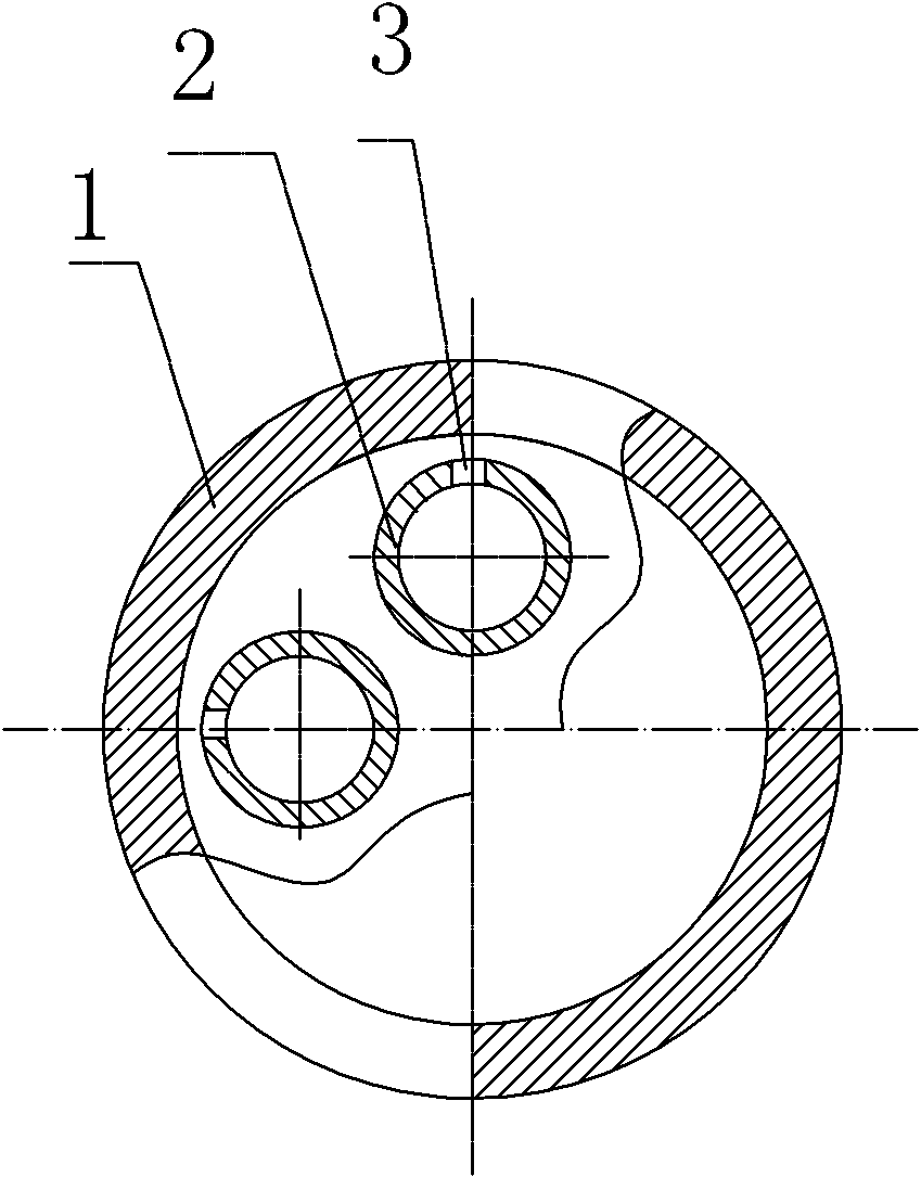
[0028] The heat exchange tube used in the evaporator of the present invention comprises an outer tube 1 and at least one inner tube 2, figure 1 It is a cross-sectional view of a single inner tube in the outer tube of the heat exchange tube used in the evaporator of the present invention, figure 2 It is a cross-sectional view of multiple inner tubes inside the outer tube of the heat exchange tube used in the evaporator of the present invention. At least one inner tube 2 is installed inside the outer tube 1 , and a plurality of jet holes 3 are arranged on the inner tube 2 . The outer tube and the inner tube can be combined in various ways, and the spray holes 3 can be arranged in various ways. The outer tube is a smooth tube or a corrugated tube. The diameter of the inner pipe is preferably 3 to 5 mm, and the diameter of the jet orifice is p...


PUM


Abstract

The invention discloses a heat exchange tube for an evaporator and the evaporator formed by the same and aims to provide a heat exchange tube capable of reducing the heat exchange area and lowering the filling quantity of refrigerants and used for an evaporator and the evaporator formed by the same. The heat exchange tube used for the evaporator comprises an outer tube and at least one inner tube, wherein the at least one inner tube is installed inside the outer tube and is provided with a plurality of spurt holes. The heat exchange tube provided by the invention adopts an inner spurt heat exchange way, high-speed flow passing through the spurt holes is sprayed on a heat exchange surface to generate turbulent flow, thereby the heat exchange coefficient of the evaporator is greatly increased, and the heat exchange area of the heat exchange tube is greatly reduced. Meanwhile, the refrigerants only flow inside the inner tube of the heat exchange tube, which greatly reduces the filing quantity of the refrigerants in a refrigerating system and greatly solves the application limit of working mediums of certain refrigerants, in particular combustible and explosive working mediums.

Description

technical field [0001] The invention relates to the technical field of evaporators, more specifically, to a heat exchange tube for an evaporator and an evaporator composed of the same. Background technique [0002] The evaporator is the most important heat exchanger in the refrigeration system. For refrigeration systems, it is a heat exchanger that absorbs heat from outside the system. The function of the evaporator is to use the liquid refrigerant to boil at low pressure, transform into vapor and absorb the heat of the cooled object or medium to achieve the purpose of refrigeration. Therefore, the evaporator is a device for producing and outputting cooling capacity in the refrigeration system. In the vapor compression refrigeration cycle, according to the cooling medium, it can be divided into air-cooled evaporator and water-cooled evaporator, and the water-cooled evaporator can be divided into flooded evaporator and dry evaporator according to the different liquid supply...

Claims


Application Information

Patent Timeline
Patent Type & Authority Applications(China)
IPC IPC(8): F28F1/00F25B39/02
Inventor 董小勇申江孙欢刘兴华侯其考李砚明
Owner TIANJIN UNIV OF COMMERCE
Why Eureka
Try Eureka