
Control system of sinter plant

A control system and controller technology, applied in the field of sintering, can solve the problems of high operation intensity, long failure time, complicated operation, etc., and achieve the effects of improving production efficiency, shortening failure time, and saving pipeline resources.

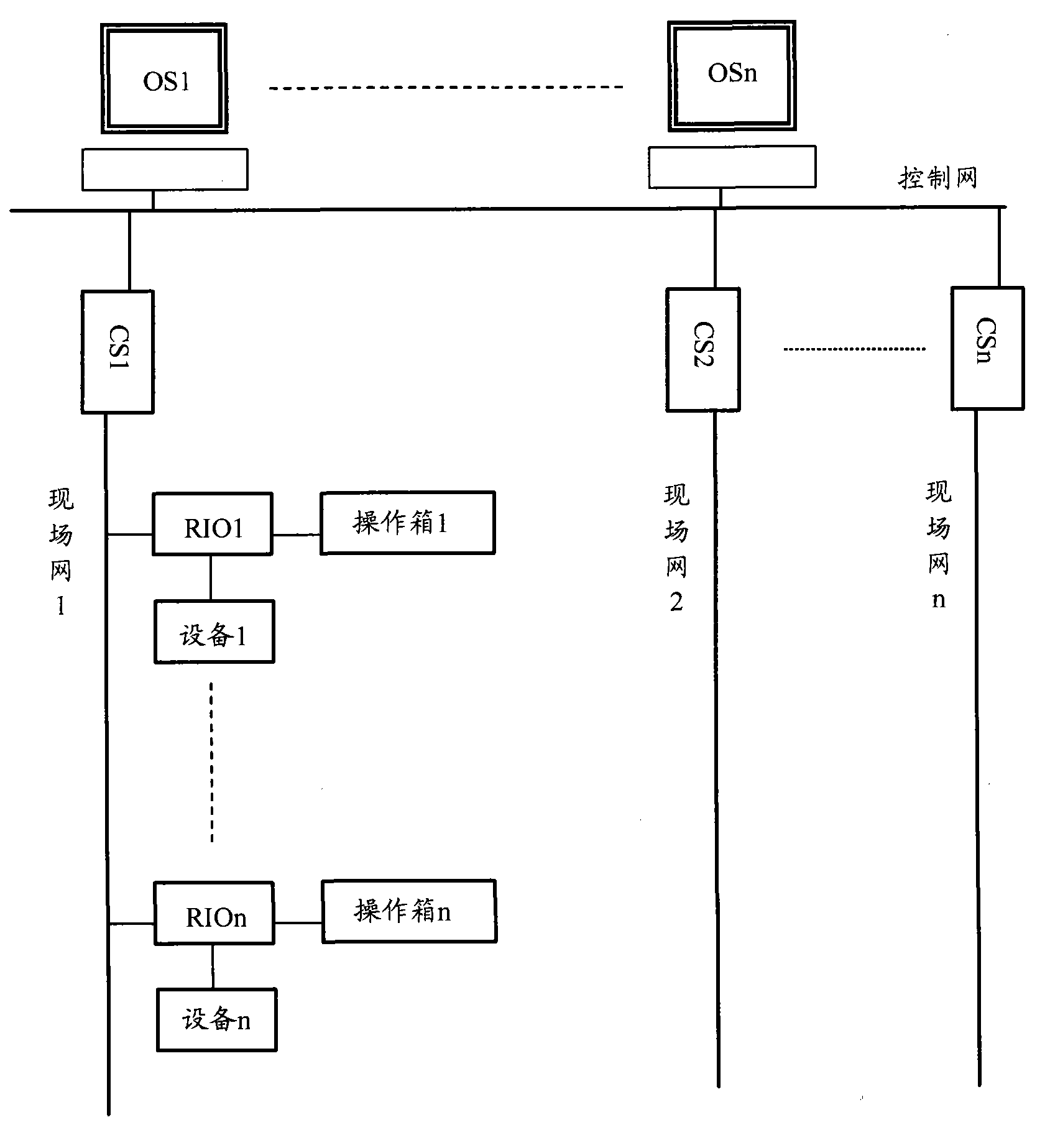
Active Publication Date: 2011-04-27
ZHONGYE-CHANGTIAN INT ENG CO LTD
View PDF0 Cites 6 Cited by
  • Summary
  • Abstract
  • Description
  • Claims
  • Application Information

AI Technical Summary

Problems solved by technology

When the tape machine breaks down, you must go to the operation box to stop the equipment, resulting in a long failure time; when debugging the tape machine, the operator must frequently go back and forth between the tail and the head of the tape machine to observe the operating status Adjustment with the operation makes the operation cumbersome and the operation intensity is too high

Method used


Image

  • Control system of sinter plant
  • Control system of sinter plant
  • Control system of sinter plant

Examples


Embodiment Construction

[0060] The purpose of the present invention is to provide a control system of a sintering plant, which can simplify site layout, reduce operation intensity, reduce failure time and improve production efficiency.

[0061] In order to make those skilled in the art understand the sintering plant control system of the present invention more clearly, detailed description will be given below in conjunction with specific drawings.

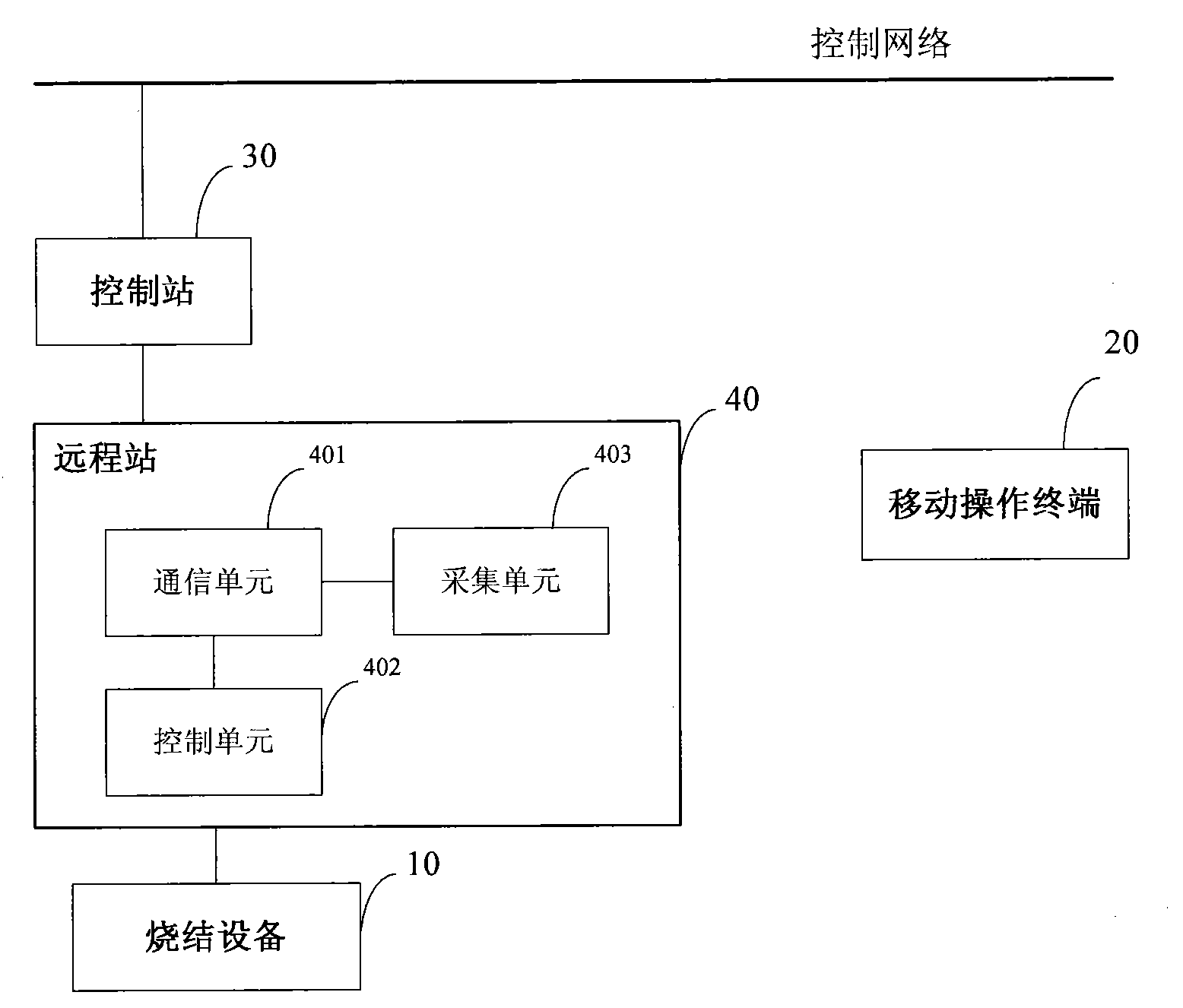
[0062] see figure 2 , is a structural diagram of the sintering plant control system according to the first embodiment of the present invention.

[0063] The system includes a sintering equipment 10 and a control network, a mobile operating terminal 20 , a control station 30 , and a remote station 40 . in,

[0064] The control station 30 is connected to the control network and is used to receive sintering equipment status information and generate sintering equipment operation instructions;

[0065] The remote station 40 is used to connect the sintering...


PUM


Abstract

The invention discloses a control system of a sinter plant, comprising a sinter apparatus, a control network, a mobile operation terminal, a control station which is connected with the control network and used for receiving state information of the sinter apparatus and generating an operation instruction for the sinter apparatus, and a remote station which is used for connecting the sinter apparatus into the control network. The remote station comprises a communication unit which is capable of receiving and transmitting a wireless signal of a specific frequency, a control unit and a collection unit; the control unit receives a wireless operation signal, which is sent from the mobile operation terminal and used for operating the sinter apparatus, through the communication unit, converts the wireless operation signal into an operation request signal, transfers the operation request signal to the control station, and receives the operation instruction returned by the control station to operate the sinter apparatus; and the collection unit is used for collecting the state information of the sinter apparatus to transmit the state information to the control station and / or to the mobile operation terminal through the communication unit. The system can simplify the site arrangement, reduce the operation intensity, reduce the fault time and improve the production efficiency.

Description

technical field [0001] The invention relates to the field of sintering, in particular to a control system of a sintering plant. Background technique [0002] The control mode of the machine-side operating system adopted by the existing sintering plant is as follows: the computer control system conducts centralized monitoring of the entire plant equipment, and the human-machine interface HMI (Human Machine Interface) operating station OS (Operating Station) in the main control room monitors the entire plant equipment. Factory production is monitored. The equipment in the process runs in linkage under the management of the computer system. When the on-site equipment fails or the equipment needs stand-alone operation (overhaul or debugging), it can be realized through the operation box on site. [0003] refer to figure 1 Shown is a typical existing sintering plant computer control system structure diagram. [0004] The existing computer control system of the sintering plant...

Claims


Application Information

Patent Timeline
Patent Type & Authority Applications(China)
IPC IPC(8): G05B19/418F27B21/14
CPCY02P90/02
Inventor 刘雁飞
Owner ZHONGYE-CHANGTIAN INT ENG CO LTD
Learn More