
Solar cell

A technology of solar cells and rear electrodes, applied in the field of solar cells, can solve the problems of reducing the covering ability of paint materials and increasing the refractive index of carrier materials, etc.

Inactive Publication Date: 2011-04-27
SCHOTT SOLAR AG (DE)
View PDF1 Cites 6 Cited by
  • Summary
  • Abstract
  • Description
  • Claims
  • Application Information

AI Technical Summary

Problems solved by technology

The disadvantage of this solution is that increasing the refractive index of the carrier substance by using the same pigments reduces the covering power of the lacquer, and in order to obtain sufficient coverage, the varnish layer must be correspondingly thicker

Method used


Image

  • Solar cell
  • Solar cell
  • Solar cell

Examples


Embodiment Construction

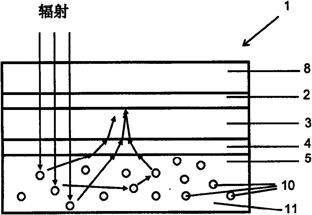
[0049] according to figure 1 , a solar cell [1] according to the prior art comprising a front electrode layer [2], a photovoltaically active absorber layer [3], a back electrode layer [4] and a layer of colored dielectric reflector [5]. figure 1 The possible ray paths of the incident radiation are also described, whereby it can be seen that light backscattered from the dielectric reflector is strongly refracted by refraction at the interface with the absorber and therefore cannot be efficiently absorbed by the absorber.

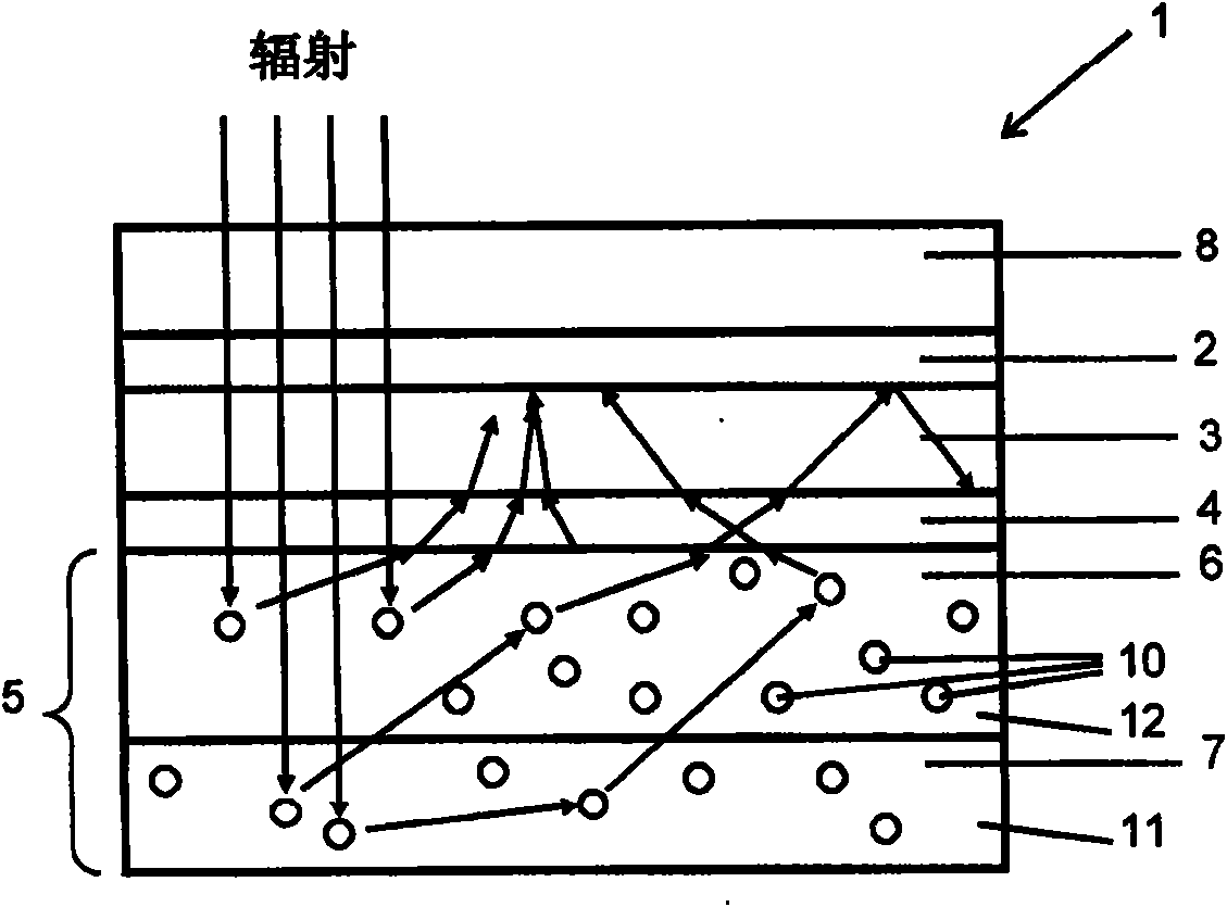
[0050] according to figure 2 , in a preferred embodiment the solar cell [1] according to the invention comprises a front electrode layer [2], a photovoltaically active absorber layer [3], a back electrode layer [4] and a colored dielectric reflector [5], The dielectric reflector [5] has a first reflector layer [6] and a second reflector layer [7]. The first reflector layer [6] contains pigments [10] in a carrier substance [12] with a high refractive index...


PUM


Abstract

The invention relates to a solar cell having a pigmented dielectric reflector which has two dielectric layers with different refractive indexes and a pigment embedded in the layer, so that the high efficiency of the solar cell is obtained under the condition of having a smaller reflector thickness. The invention also relates to a material system applicable to manufacturing the dielectric reflector.

Description

technical field [0001] The invention relates to solar cells with dielectric colored reflectors. Background technique [0002] Solar cells of different designs often have back reflectors, which increase the optical path of the radiation through the photovoltaic cell, resulting in improved absorption and thus the efficiency of the solar cell. [0003] On the other hand, metallic reflectors, eg made of Al or Ag, are known from the prior art, which produce a directional metallic reflection of incident radiation. When the solar cell is oriented perpendicular to the main radiation source and the reflector layer is flat, the optical path through the photovoltaic absorber can thus be roughly doubled. The optical reflector may also have a microstructured rough surface so that some radiation is reflected obliquely with respect to the light incidence axis and thus has a longer optical path through the absorber. [0004] The prior art also discloses the use of tinted dielectric reflec...

Claims


Application Information

Patent Timeline
Patent Type & Authority Applications(China)
IPC IPC(8): H01L31/052
CPCY02E10/52H01L31/0527H01L31/056
Inventor 沃尔克·哈格曼马蒂亚斯·布克梅尔彼得·莱希纳迈克尔·贝尔金斯基
Owner SCHOTT SOLAR AG (DE)
Learn More