Power confluence method of multiple high altitude wind generating sets for intermittent power generation

A technology of wind power generating set and power, which is applied in the direction of wind power motor combination, wind power engine, engine, etc. It can solve the problems of large generator capacity, tether winding, and infeasibility, so as to reduce the demand of control design, flexible installation position, Good output stability

Inactive Publication Date: 2011-04-27
DONGFANG TURBINE CO LTD
View PDF6 Cites 2 Cited by
  • Summary
  • Abstract
  • Description
  • Claims
  • Application Information

AI Technical Summary

Problems solved by technology

The disadvantages of [0010] mechanical confluence are;
[0011]1. To combine multiple powers, the differential gear train needs to have a corresponding number of input shafts, and it is often necessary to design a multi-stage differential structure, which is too complicated and expensive high
A wind farm usually has dozens or even hundreds of units, it is impossible to use a differential gear train to achieve confluence, and it is still necessary to divide and combine flows, and the smoothness of the output power curve is limited
[0012]2. According to experience, the distance between high-altitude wind energy generator sets should not be less than the tether length of the working part, and the scale can reach several kilometers, but the differential gear It is impossible to design the size of the wind turbine very large, which limits the mutual distance between the high-altitude wind energy generators. If the distance is too small, the tethers of the aerial work parts may be entangled in the air, causing accidents
[0013]3. The confluence method is to combine the mechanical power first, and then generate electricity, that is to say, use multiple aerial power umbrellas to drive a generator to generate electricity, so the generator capacity Large, lack of maneuverability, when part of the air power parachute exits for some reason, the efficiency of the generator is low
[0014] Therefore, in the large-scale application of high-altitude wind power generation, it is basically infeasible to adopt the method of mechanical confluence

Method used


Image

  • Power confluence method of multiple high altitude wind generating sets for intermittent power generation
  • Power confluence method of multiple high altitude wind generating sets for intermittent power generation
  • Power confluence method of multiple high altitude wind generating sets for intermittent power generation

Examples


example 1

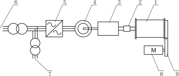
[0030] see figure 2 : The wind power generating set includes air parachute and ground part, the ground part is composed of reel 1, one-way clutch 2, gear box 3, generator 4, full power converter 5, auxiliary motor 8, and the auxiliary motor passes through the transmission mechanism 9 connect the reel 1. The aerial work parachute floats in the air, and its tether is wound on the reel 1. In order to prevent the reel 1 from driving the generator 4 to reverse, a one-way clutch 2 is installed between the reel 1 and the speed-increasing gear box 3. The movement between the generators 4 is disengaged, and the generators 4 do not reverse. The output side of the full power converter 5 is provided with a self-use electrical port 7 for supplying power to the auxiliary motor 8 .

[0031] Its working principle is that when the aerial power-working parachute rises against the wind, the tether traction reel 1 rotates, speeds up through the gear box 3, and drives the generator 4 to genera...

example 2

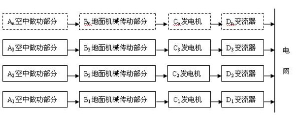
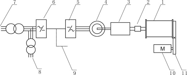
[0033] see image 3 : Its basic structure and diagram 2 Roughly the same, only the choice of confluence point of power is different. It consists of a drum 1, a one-way clutch 2, a gearbox 3, a generator 4, a rectifier 5, an inverter 6, an auxiliary motor 10, and a transmission mechanism 11. There is a grid-connected output terminal 7 and an auxiliary motor power supply terminal 8 . The difference is that the confluence node 9 is the DC bus bar of the converter. figure 2 and image 3 The difference between the proposed electrical confluence methods lies in the selection of the power confluence points of multiple high-altitude wind energy generator sets. figure 2 The power confluence point is selected at the AC end of the converter, and image 3 Choose to merge at the DC busbar, and different choices of junction points will bring different requirements for components, especially inverters. For the confluence mode of the AC side, the capacity of the inverter is equal to the...


PUM


Abstract

The invention discloses a power confluence method of multiple high altitude wind generation sets for intermittent power generation, comprising the following steps of: respectively obtaining wind power from an air work-applying umbrella of each high altitude wind generating set, transmitting the obtained wind power to a ground winding drum by a tether, converting the obtained wind power into a mechanical power so as to drive a generator to generate electricity after accelerated by a gearbox, converting the current into a power-frequency three-phase AC (Alternating Current) by a full-power converter, and then carrying out the confluence of the power-frequency three-phase AC output by all high altitude wind generating sets and merging into the power network. By the technical scheme of the invention, the shortage of mechanical confluence can be overcome, and the power confluence of multiple high altitude wind generation sets for intermittent power generation is feasible.

Description

technical field [0001] The invention relates to wind power generation technology, in particular to a method for converging power of high-altitude wind power generating sets with multiple intermittent power generation. Background technique [0002] Wind energy has become one of the most practical forms of renewable energy due to its advantages of wide distribution, reusability and mature technology. The most common way to use wind energy in the past few decades is to capture wind energy to generate electricity through wind turbines equipped with wind rotors. At present, most of the wind turbines of wind turbines operate in the lower part of the near-earth boundary layer, where the annual average wind speed is usually 4-6m / s, and the wind energy density is not high. The power generation and capacity factor are small. If the wind turbine is made larger and the economy is improved through a larger single-unit capacity, it will bring about an increase in the size of the whole ma...

Claims


Application Information

Patent Timeline
Patent Type & Authority Applications(China)
IPC IPC(8): H02J3/38F03D9/00
CPCY02E10/72Y02E10/763Y02E10/725Y02E10/76
Inventor 刘桦王建录王兵莫尔兵邓良王为民
Owner DONGFANG TURBINE CO LTD
Why Eureka
Try Eureka