Method and device for heating down-draft biomass gasifier by exhaust gas of engine

A gasifier and biomass technology, which is applied to exhaust devices, engine components, combustion engines, etc., can solve the problems of insufficient temperature and difficult to achieve tar cracking, and achieve the effect of solving purification problems, easy implementation and simple device structure.

Inactive Publication Date: 2011-05-04
YANGZHOU POLYTECHNIC INST
View PDF4 Cites 2 Cited by
  • Summary
  • Abstract
  • Description
  • Claims
  • Application Information

AI Technical Summary

Problems solved by technology

The disadvantage of the above-mentioned patents is that "the thermal cracking of tar is carried out in the detour channel of the gas flow", which requires a temperature of more than 1100°C to obtain a higher conversion rate. Obviously, the temperature here is not enough; if "a catalytic cracking bed is added at the bottom of the furnace" , the gas must reach a certain temperature for the catalytic cracking reaction to occur when the gas flows through the cracking bed, and this place is located at the bottom of the gasification furnace body, and it is difficult to achieve the purpose of tar cracking due to the low temperature
[0005] In the practical application of dual-fuel engines using biomass gas and gasoline, it has not yet occurred to use the exhaust gas from the engine to heat the materials in the gasifier by means of partition wall heating to provide heat for the gasifier and increase the biomass gasification temperature and promote Gasification device for catalytic cracking of tar in gas

Method used


Image

  • Method and device for heating down-draft biomass gasifier by exhaust gas of engine
  • Method and device for heating down-draft biomass gasifier by exhaust gas of engine

Examples


Embodiment Construction

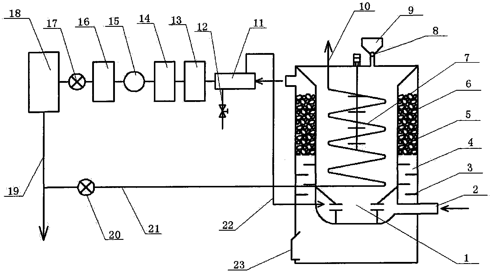
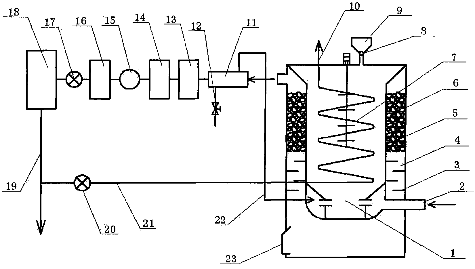
[0023] As shown in the drawings, the biomass gasification equipment in the embodiment of the present invention adopts a fixed-bed downdraft biomass gasification furnace 1, and the biomass raw material is fed from the hopper 9, and the material falls into the furnace through the feeding mechanism 8, and passes through layers The slide moves gradually towards the bottom of the furnace. Air, which is one of the gasification agents, enters from the air inlet pipe 2 . The biomass is first dried in the furnace, and after reaching a certain temperature, it undergoes pyrolysis and precipitates volatile matter, and then undergoes oxidation and reduction reactions with the gasification agent; the ash produced by the biomass after fully reacting falls into the ash chamber at the lower part of the gasification furnace , the ash chamber is provided with ash outlet 23. The fuel gas generated by the reaction in the gasification furnace flows upwards from the lower part of the furnace body t...


PUM


Abstract

The invention discloses a method and device for heating a down-draft biomass gasifier by exhaust gas of an engine, comprising a biomass gasifier, a double-fuel engine, a heat exchanger and the like. In the invention, high-temperature waste gas exhausted by the double-fuel engine is partly led into a spiral tube arranged in the gasifier to heat materials in the gasifier, thereby raising the biomass gasification temperature and the temperature of a catalytic cracking chamber in the furnace and benefiting the cracking of tar in gas, in the furnace. The heat exchanger arranged at the outlet of the gasifier can supply self-production steam to the gasifier and enables the gas to be condensed and cooled to realize the purpose that the steam and the air are used as a gasification agent. Compared with a down-draft biomass gasifier usually taking air as the gasification agent, the down-draft biomass gasifier provided by the invention ensures that a heat value of the gas is enhanced by above 20 percent. The device can integrate biomass gasification and catalytic cracking of the tar in the furnace, efficiently solve the problem of purification of the tar in the gas to enable the tar content to be lowered by above 60 percent in comparison with the tar content in the gas of an ordinary fixed-bed gasifier and has the advantages of simple structure, little flowing resistance and easiness for implementation.

Description

technical field [0001] The invention relates to a gasification furnace, in particular to a method and a device for heating materials in a downdraft biomass gasification furnace by using exhaust gas discharged from an engine in a partition heating manner, and belongs to the technical field of biomass gasification utilizing renewable energy. Background technique [0002] In the field of biomass gasification, the commonly used fixed bed gasification method generally uses air as the gasification agent. Although the structure is simple, there are problems such as low calorific value of gas, low gasification efficiency, and high tar in the gas produced by the gasifier. . The reaction temperature in the gasifier has a great influence on the gas composition and calorific value; increasing the gasification reaction temperature can improve the efficiency of the gasifier, promote the thermal cracking of tar, and reduce the tar content in the gas. [0003] Zhu Huabing, Hu Kongyuan, Che...

Claims


Application Information

Patent Timeline
Patent Type & Authority Applications(China)
IPC IPC(8): C10J3/20C10J3/60C10J3/84C10J3/80C10J3/72F01N5/00F02B43/08
CPCY02T10/12Y02T10/30
Inventor 王武林周平范丛山刘伯玉王昕明
Owner YANGZHOU POLYTECHNIC INST
Why Eureka
Try Eureka