
Control device of automotive air conditioning electrical equipment and using method thereof

A control device, a technology for automotive air conditioners, applied in heating and ventilation control systems, applications, household heating, etc., can solve problems such as inability to work with temperature servo motors, inability to control electrical devices, and inconvenience for testing and simulation.

Inactive Publication Date: 2013-03-06
SHANGHAI BEHR THERMAL SYST
View PDF0 Cites 0 Cited by
  • Summary
  • Abstract
  • Description
  • Claims
  • Application Information

AI Technical Summary

Problems solved by technology

For system development, it is not convenient for testing and simulation
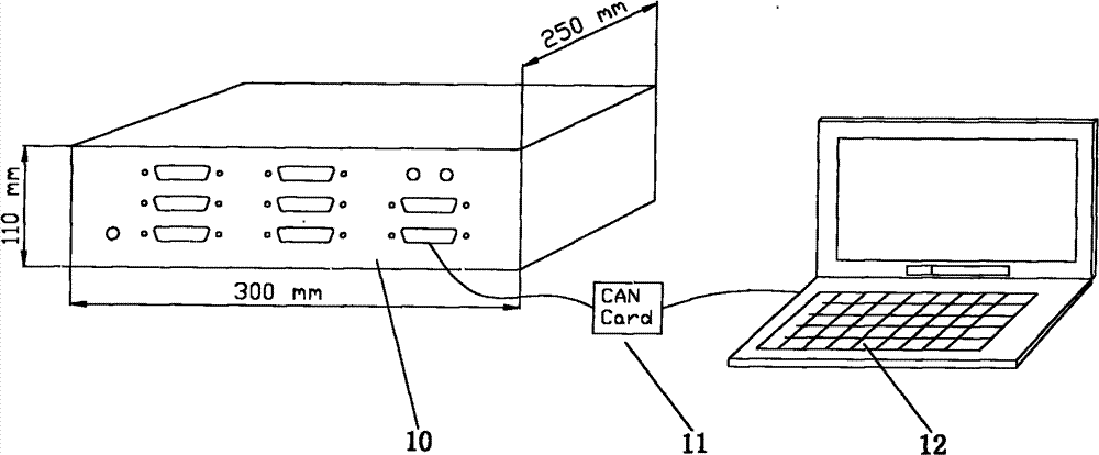
[0003] There are two traditional control methods for air-conditioning electrical components. One is a small controller. This small controller can only simply control a single air-conditioning electrical component, or can only be used in a single project, and cannot be controlled according to different conditions. It is required to configure the parameters. For example, the controller of the DC motor currently used determines the feedback voltage value of each motor according to the Rover project, so the motor can only run to the feedback voltage value, such as controlling the motor of each air outlet mode , the feedback voltage values ​​corresponding to different modes are determined in the original control box according to the design of the Rover project, and are unique. If you change a project, the feedback voltage values ​​​​corresponding to each air outlet mode are different, so you cannot adjust , and the control box can freely set the corresponding feedback voltage value on the host computer interface according to the requirements of different air outlet modes
The second way is to use the air conditioner control panel on the real car to control. Since the whole car currently uses CAN BUS for data transmission, it cannot be separated from the environment of the whole car when using the control head to adjust, so it is impossible to control the electrical components.
For example, when using an automatic air conditioner, the controller will change the direction of the temperature damper in real time according to the temperature inside the car, and the temperature inside the car will be collected and transmitted through the CAN bus. The temperature damper is controlled by a temperature servo motor, which is out of the vehicle environment After that, the temperature data cannot be transmitted to the controller. Without these data, the controller cannot make the temperature servo motor work.

Method used


Image

  • Control device of automotive air conditioning electrical equipment and using method thereof
  • Control device of automotive air conditioning electrical equipment and using method thereof
  • Control device of automotive air conditioning electrical equipment and using method thereof

Examples


Embodiment 1

[0052] In this embodiment, a functional board 3 is connected to and controls a DC servo motor with a potentiometer. When in use, input the parameters that need to be set into the interface, and after the control box processes these parameters, the motor will run, display relevant parameters, and obtain the results required by the user.

[0053] The control principle of the function board with potentiometer servo motor used in this embodiment is as follows: Figure 6 As shown, the motor rotates, drives the brush through the transmission gear, and the brush touches the potentiometer on the circuit board to form an H bridge through Q1, Q2, Q3, and Q4. When MCU-C1 and MCU-C2 are 10 or 01 respectively, the control Motor forward and reverse. Resistor R1 is used for current collection, and the collected signal is used for motor control.

[0054] Such as Figure 10 As shown, the working process of the function board with potentiometer servo motor is as follows: determine the forwar...

Embodiment 2

[0056] In this embodiment, a functional board 3 is connected to and controls a DC servo motor with contacts. When in use, input the parameters that need to be set into the interface, and after the control box processes these parameters, the motor will run, display relevant parameters, and obtain the results required by the user.

[0057] The control principle of the functional board of the DC servo motor with contacts used in this embodiment is as follows: Figure 7 As shown, resistor R1 is used for current collection, and the collected signal is used for motor control.

[0058] Such as Figure 11 As shown, the working process of the function board of the DC servo motor with contacts is as follows: determine the corresponding contacts of each point; click the required contact signal button; judge whether the current is greater than the stall current, if so, emergency stop, If not, the motor runs.

Embodiment 3

[0060] In this embodiment, a function board 3 is connected to and controls a temperature sensor, and the function board 3 is an analog acquisition board. Such as Figure 12 As shown in , the analog acquisition board collects the resistance value of the temperature sensor, so as to judge whether the working state of the temperature sensor is normal, short circuit or open circuit. The steps are as follows:

[0061] 1) Collect the resistance value of the temperature sensor;

[0062] 2) Determine whether the resistance value is in the normal range, if the resistance value is in the normal range, if the resistance value is in the normal range, the temperature sensor is working normally; if the resistance value is zero, the temperature sensor is short-circuited; if the resistance value is infinite, the temperature sensor Sensor open circuit.


PUM


Abstract

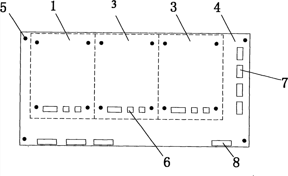
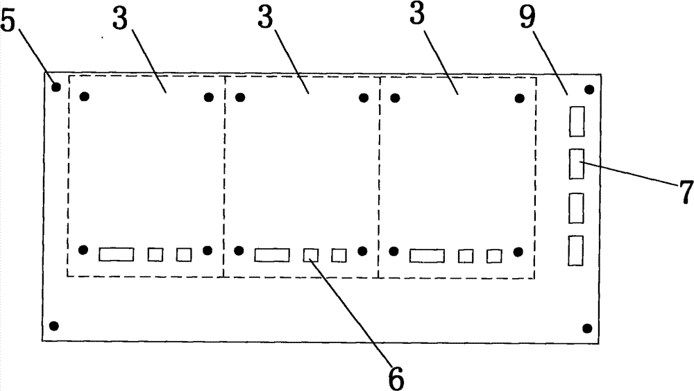
The invention discloses a control device of automotive air conditioning electrical equipment and a using method thereof. The control device comprises a control box, a bus card and a control unit; the control box comprises a mother board, a bus board and at least one functional plugboard; the bus board is arranged on the mother board; the bus board comprises a data bus and a control bus; the data bus and the control bus are respectively connected with the mother board and the functional plugboard; the bus card is respectively connected with the bus board and the control unit, the bus board andthe control unit exchange data through the bus card in bothway; the functional plugboard is connected with and controls at least one electrical equipment, and the control unit controls the electricalequipment by the functional plugboard so as to judge whether the electrical equipment normally works or not. The control device can drive the air conditioning electrical equipment away from the environment of the whole car, and can set parameters flexibly toachieve the purpose of meeting the requirement of different car types.

Description

technical field [0001] The invention relates to an electric appliance control device, in particular to a control device and a use method of an automobile air-conditioning electrical device that can be separated from the vehicle environment. Background technique [0002] Air-conditioning electrical components include blowers and blower regulators, servo motors, and sensors. To drive these electrical components, the air-conditioning control head must be used. With the continuous development of automobile technology, more and more vehicles use CAN BUS for data transmission of various devices. Even if there is a control head, it must be driven in the environment of the vehicle. For system development, it is not convenient for testing and simulation. [0003] There are two traditional control methods for air-conditioning electrical components. One is a small controller. This small controller can only simply control a single air-conditioning electrical component, or can only be u...

Claims


Application Information

Patent Timeline
Patent Type & Authority Patents(China)
IPC IPC(8): F24F11/00F24F11/02
Inventor 华树芬
Owner SHANGHAI BEHR THERMAL SYST
Learn More