
Inherent frequency measuring device for 600 DEG C high-temperature thermal vibration coupling test of high-speed cruise missile airfoil surface

A cruise missile and natural frequency technology, applied in measuring devices, measuring ultrasonic/sonic/infrasonic waves, instruments, etc., can solve problems such as redness and softening, high temperature resistant acceleration sensors cannot be used normally, and achieve the effect of reducing special requirements

Inactive Publication Date: 2011-05-04
BEIHANG UNIV
View PDF4 Cites 12 Cited by
  • Summary
  • Abstract
  • Description
  • Claims
  • Application Information

AI Technical Summary

Problems solved by technology

The metal material used to make the acceleration sensor will also appear red and soften at 600°C, and its thermal expansion, Poisson's ratio, and elastic modulus and other material parameters will change greatly with the change of high-temperature environment. Normal use in high dynamic high temperature thermal environment

Method used


Image

  • Inherent frequency measuring device for 600 DEG C high-temperature thermal vibration coupling test of high-speed cruise missile airfoil surface
  • Inherent frequency measuring device for 600 DEG C high-temperature thermal vibration coupling test of high-speed cruise missile airfoil surface
  • Inherent frequency measuring device for 600 DEG C high-temperature thermal vibration coupling test of high-speed cruise missile airfoil surface

Examples


Embodiment Construction

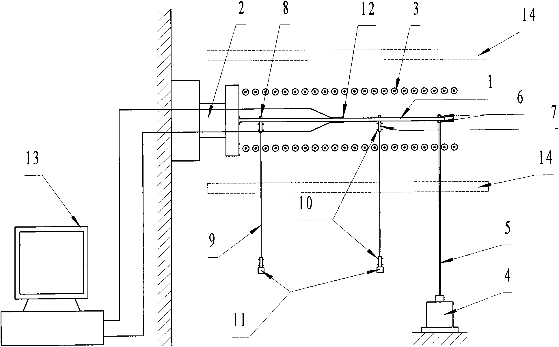
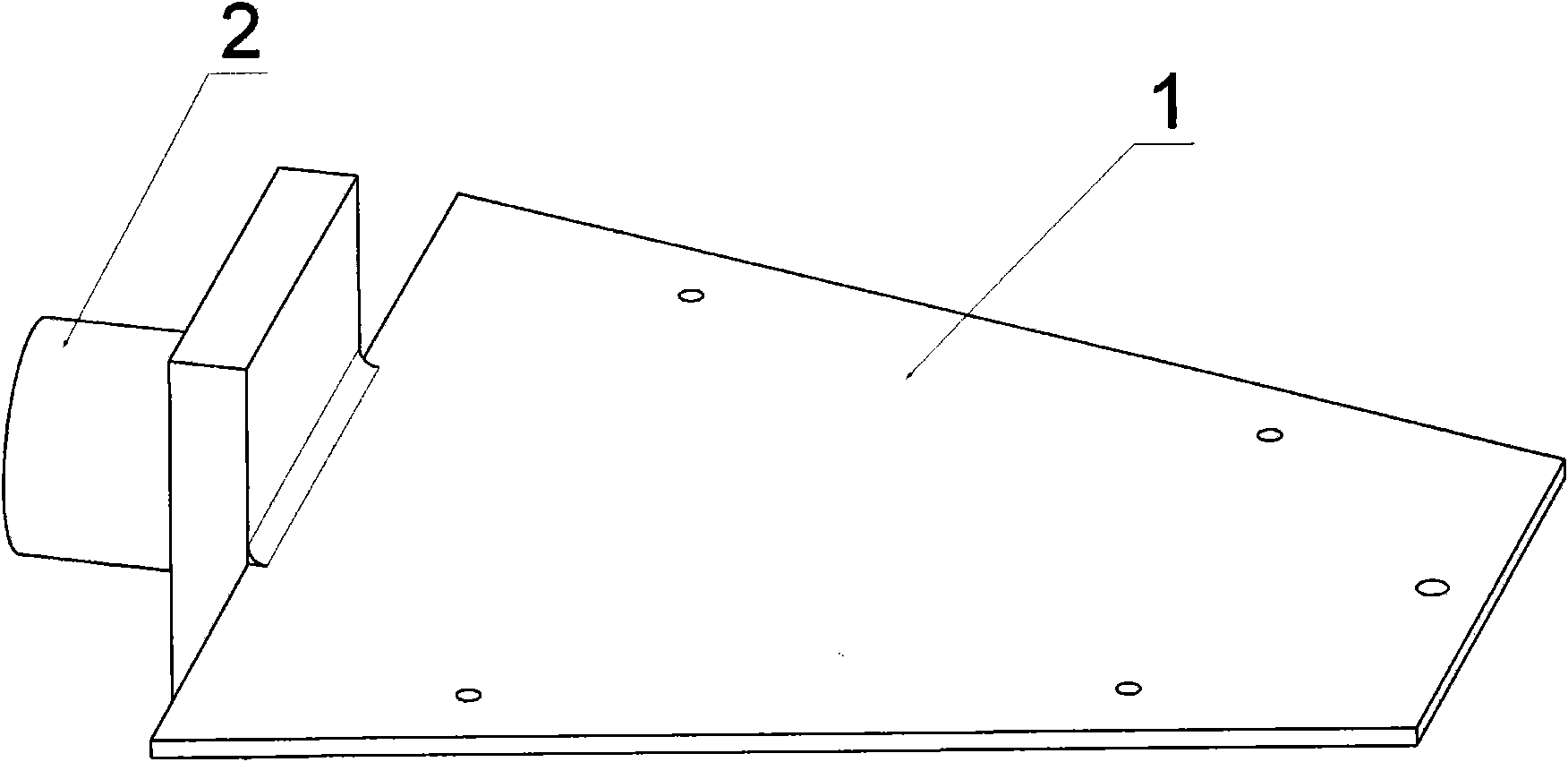
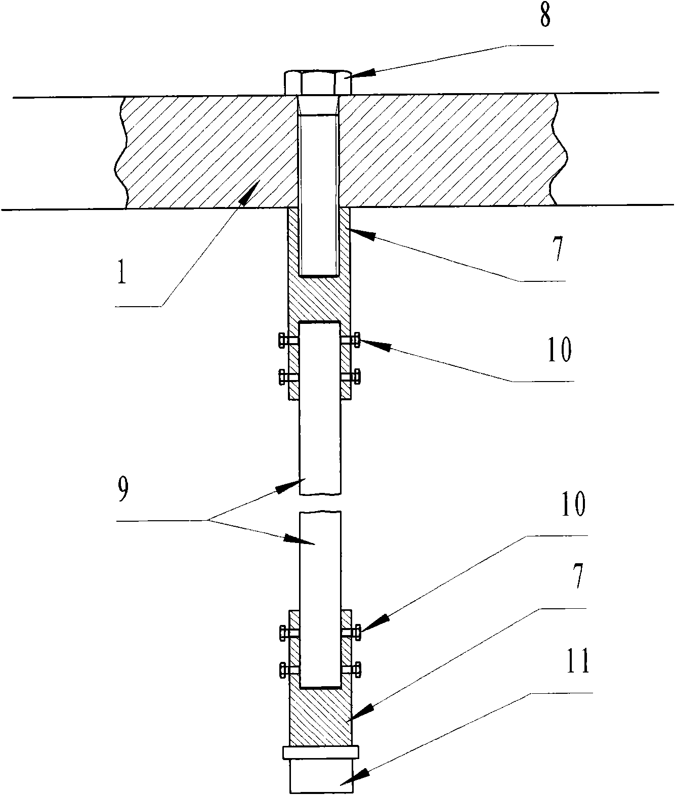
[0022] Such as figure 1 , figure 2 with image 3 As shown, the present invention consists of a missile airfoil structure test piece 1, a fixed support 2, a quartz lamp heating array 3, an exciter 4, an excitation guide rod 5, a locking nut 6, a copper coupling sleeve 7, and a coupling bolt 8. Ceramic extension rod 9, locking bolt 10, acceleration sensor 11, temperature sensor 12, computer 13 and heat insulation baffle 14.

[0023] The metal missile airfoil structure test piece 1 is welded on the fixed support 2, and a row of quartz lamp heating arrays 3 are respectively arranged at a distance of about 50mm from the upper and lower surfaces of the missile airfoil structure test piece 1, and the missile airfoil structure test piece 1 The upper and lower surfaces are heated to simulate the aerodynamic thermal environment of the cruise missile wing during high-speed flight. The vibrator 4 is firmly connected with the missile airfoil structure test piece 1 through the locking n...


PUM

PropertyMeasurementUnit
Diameteraaaaaaaaaa

Abstract

The invention discloses an inherent frequency measuring device for 600 DEG C high-temperature thermal vibration coupling test of a high-speed cruise missile airfoil surface. The device comprises a missile airfoil surface structure test piece, a quartz lamp heating array, a vibration exciter, a ceramic extension rod, an acceleration transducer, a computer and a heat insulation baffle plate. In the high-temperature thermal vibration coupling test of the cruise missile airfoil surface, the missile airfoil surface is quickly heated by using the quartz lamp heating array and generates random vibration through the vibration exciter at the same time to form a 600 DEG C high-temperature thermal vibration coupling test environment. The rigid ceramic extension rod with high rigidity and high temperature resistance is arranged on the missile airfoil surface to guide the vibration signals on the missile airfoil surface out of the high-temperature thermal field, and the high-temperature resistant lightweight ceramic fiber heat insulation baffle plate is used for implementing thermal diffusion prevention shielding for the radiation thermal field. The normal temperature acceleration transducer arranged at the cold end of the ceramic extension rod dynamically tracks and measures the vibration signals guided to the missile airfoil structure of the normal temperature zone to acquire the change rule of the inherent frequency of the missile airfoil surface under the high-temperature thermal vibration coupling test environment; and the device provides an effective dynamic high-temperature thermal vibration coupling test means for researching and manufacturing high-speed cruise missiles.

Description

technical field [0001] The invention relates to a device for measuring the natural frequency of a 600°C high-temperature thermal-vibration coupling test of a high-speed cruise missile wing surface, especially when the cruise missile supersonic flight aerodynamic thermal test environment simulation is carried out, the test device can measure and measure the natural frequency under high-temperature conditions up to 600°C. The changing law of the natural frequency of the missile airfoil structure under severe vibration provides a reliable basis for the safety design of the cruise missile airfoil structure in a high-speed, high-temperature thermal-vibration coupling environment. Background technique [0002] Cruise missile is an advanced weapon with wide application, relatively low manufacturing cost and high combat effectiveness. It has the characteristics of long range, sudden attack, high hit accuracy, and strong destruction ability. Therefore, many countries in the world at...

Claims


Application Information

Patent Timeline
IPC IPC(8): G01H17/00
Inventor 吴大方潘兵黄良梁伟
Owner BEIHANG UNIV
Learn More