Catalytic cracking regeneration process and equipment with low NOx emission
A catalytic cracking and process technology, applied in the petrochemical field, can solve the problems of catalyst additive poisoning, deactivation, and not being well solved, and achieve the effect of reducing NOx emission, realizing NOx emission and low NOx emission.
- Summary
- Abstract
- Description
- Claims
- Application Information
AI Technical Summary
Problems solved by technology
Method used
Image


Examples
Embodiment 1
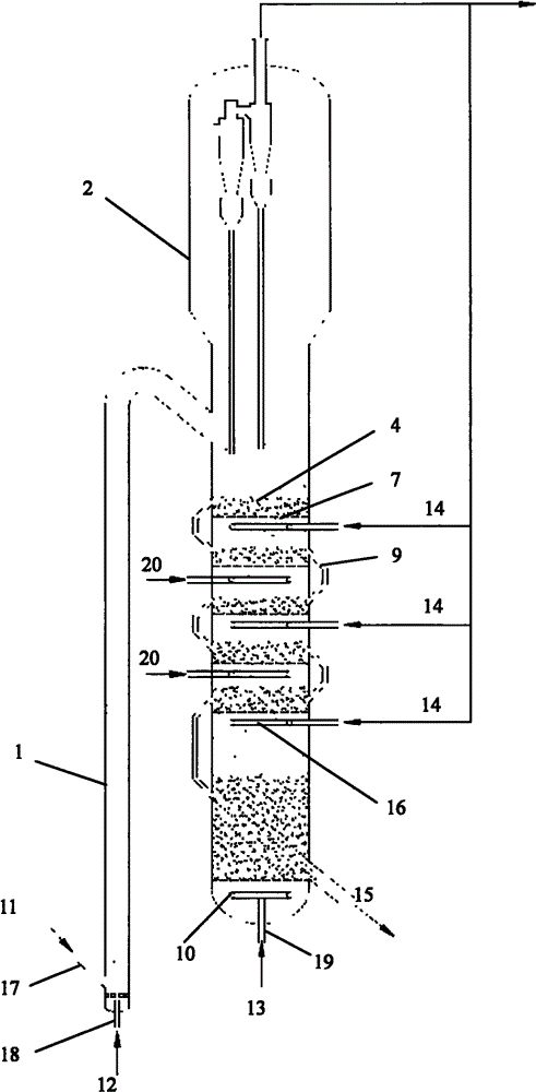
[0030] a low NO x Discharged catalytic cracking regeneration equipment, the equipment includes a riser regenerator 1 and a multi-stage counter-current fluidized bed regenerator 2, the riser regenerator 1 is connected in series with the multi-stage counter-current fluidized bed regenerator 2, and the The multi-stage countercurrent fluidized bed regenerator 2 is provided with a plurality of gas distribution plates 7, the gas distribution plates 7 are provided with overflow risers 9, and the overflow risers 9 are external or built-in. A plurality of gas distributors 16 are arranged in the middle of the multi-stage countercurrent fluidized bed regenerator 2 , and the number of the gas distributors 16 is 3 to 7, and the gas distributors can be dispersedly arranged under the gas distribution plate 7 .
[0031] The riser regenerator 1 and the multi-stage countercurrent fluidized bed regenerator 2 are arranged coaxially or in parallel. When they are arranged coaxially, a baffle plate ...
Embodiment 2
[0037] low NO used x Five annular gas distributors 16 (see Image 6 ), the multi-stage countercurrent fluidized bed regenerator 2 is provided with a plurality of gas distribution plates 7 , and the gas distributors can be distributed under the gas distribution plates 7 . The riser regenerator 1 and the multi-stage countercurrent fluidized bed regenerator 2 are arranged in parallel, and the gas distribution plate 7 is provided with an overflow riser 9, which is external. The device such as figure 1 shown.
[0038] a low NO x Emissions from the catalytic cracking regeneration process, combined with the given figure 1 The processing method of the present invention is further described:
[0039] The to-be-grown catalyst 11 from the catalytic cracking reactor enters the riser regenerator 1 from the catalyst inlet 17 of the riser regenerator 1, and the air 12 enters from the air inlet 18 at the bottom of the riser regenerator 1, and flows upward with the un-grown catalyst. The...
Embodiment 3
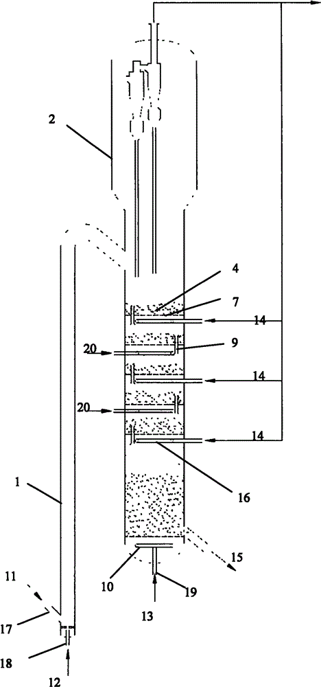
[0046] The equipment used in this example is the same as that in Example 2 except that the catalyst overflow riser 9 of the countercurrent regenerator 2 is built-in. The equipment used in this example is as follows figure 2 shown.
[0047] a low NO x Emissions from catalytic cracking regeneration processes such as figure 2 As shown, its technological process is identical with embodiment 1, adopts following technological parameters:
[0048] The top pressure of the riser regenerator is 0.23MPa (gauge pressure), the reaction temperature is 660°C, and the gas superficial linear velocity of the air 12 is 1.5m / s. In the riser regenerator 1, control The excess oxygen content is 0.7%, which burns off 40% of the carbon and most of the hydrogen.
[0049] The superficial linear velocity of the gas in the multi-stage countercurrent fluidized bed regenerator 2 is 1.1 m / s, the top pressure is 0.23 MPa (gauge pressure), and the regeneration temperature is 690°C.
[0050] In the multi...
PUM
 Abstract
Description
Claims
Application Information
 - R&D
- Intellectual Property
- Life Sciences
- Materials
- Tech Scout
- Unparalleled Data Quality
- Higher Quality Content
- 60% Fewer Hallucinations
Browse by: Latest US Patents, China's latest patents, Technical Efficacy Thesaurus, Application Domain, Technology Topic, Popular Technical Reports.
© 2025 PatSnap. All rights reserved.Legal|Privacy policy|Modern Slavery Act Transparency Statement|Sitemap|About US| Contact US: help@patsnap.com