Optical glass bubbler

A technology of optical glass and bubbler, which is applied in glass furnace equipment, glass manufacturing equipment, manufacturing tools, etc., can solve the problems that affect the internal quality of optical glass and is not suitable for optical glass production, and achieve faster melting efficiency and uniform glass color Consistent, color-suppressing effect

Inactive Publication Date: 2011-05-11
北方光电股份有限公司
View PDF7 Cites 7 Cited by
  • Summary
  • Abstract
  • Description
  • Claims
  • Application Information

AI Technical Summary

Problems solved by technology

This kind of bubbler often brings impurities into the glass liquid, which affects the internal quality of optical glass, and is not suitable for the production of optical glass

Method used


Image

  • Optical glass bubbler
  • Optical glass bubbler

Examples


Embodiment Construction

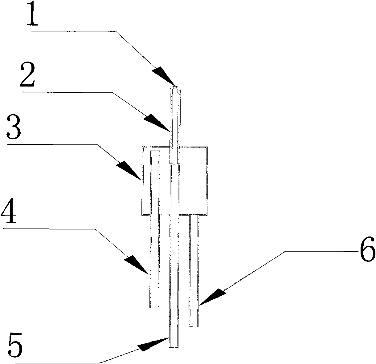
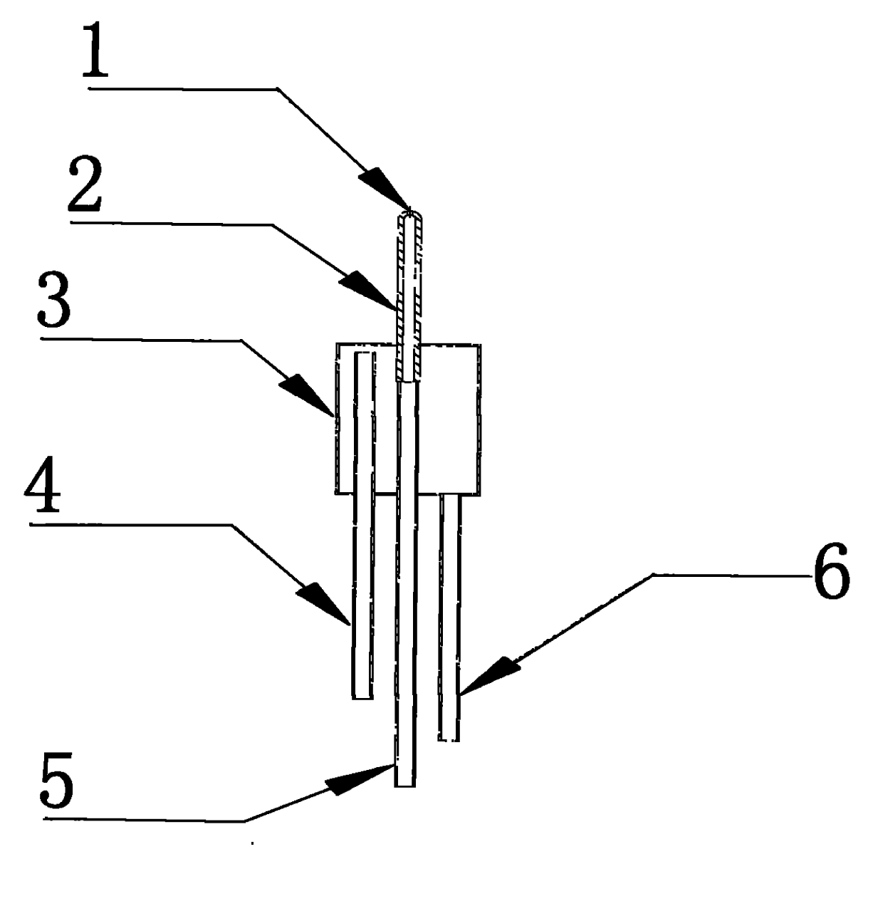
[0011] Such as figure 1 shown. The optical glass bubbler is composed of an air outlet 1, an air outlet pipe 2, a cooler 3, a water outlet pipe 4, an air inlet pipe 5 and a water inlet pipe 6. The air inlet pipe 5 is welded together with the air outlet pipe 2 to form a channel for compressed air. The cooler 3 is coaxial with the air outlet pipe 2, the air outlet pipe 2 passes through the cooler 3, and the seams are welded. The cooler 3 forms a closed circulating water space, and the water outlet pipe 4 and the water inlet pipe 6 are welded at the lower end. The device of the invention is welded by platinum material. The device of the present invention can also be welded with palladium gold or rhodium gold materials.

[0012] Before the masonry melting pool is built, the cavity of the bubbler is reserved for the molten bottom brick. The size of the cavity must be coaxial, and the diameter of the cavity is slightly larger than the diameter of the corresponding part of the bub...


PUM


Abstract

The invention relates to an optical glass bubbler, and belongs to the technical field of optical glass smelting devices. The optical glass bubbler mainly solves the problems of low efficiency, long time for replacing glass marks, low yield and unsuitability for replacing the glass marks in the mode of homogenizing glass liquid by the conventional smelting furnace through heat convection. The optical glass bubbler is mainly characterized by comprising a bubbling pipe and a cooler, wherein the cooler is a sealing box body and is sleeved outside the bubbling pipe, and a water inlet pipe and a water outlet pipe which are connected with a circulating system are arranged at the lower end of the cooler; the bubbling pipe is formed by connecting an air inlet pipe and an air outlet pipe, the air outlet pipe extends out of the upper side of the center of the cooler, and the air inlet pipe extends out of the lower side of the cooler; and an air outlet is formed at the upper end of the air outlet pipe. The optical glass bubbler has the characteristics of realizing the intense convection of the glass liquid in a smelting pond and regulating oxidoreduction atmosphere in the glass liquid, along with anti-blocking effect, and is mainly used for smelting optical glass and colored glass.

Description

technical field [0001] The invention belongs to the technical field of optical glass melting devices. Specifically relates to an optical glass bubbler suitable for melting optical glass, colored glass, etc., which can realize sufficient mixing, convection and atmosphere adjustment of glass liquid in a melting pool, and control the gas ratio of glass liquid. Background technique [0002] Optical glass manufacturing equipment is generally relatively small, and the output of the more common furnaces is 0.5 tons / day to 3 tons / day. This kind of melting furnace is suitable for the market demand of optical glass with many varieties (hundreds of grades) and small batches. Because optical glass has strict requirements on internal indicators such as refractive index fluctuation, uniformity, bubble degree, and striae degree, the yield rate of the product is relatively low. Ordinary optical glass furnaces are produced by porcelain-platinum continuous melting production lines. In order...

Claims


Application Information

Patent Timeline
IPC IPC(8): C03B5/193
CPCC03B5/193
Inventor 姜敬陆
Owner 北方光电股份有限公司
Why Eureka
Try Eureka