Data shuffling unit with switch matrix memory and shuffling method thereof

A switch matrix and memory technology, applied in the data shuffling unit and its shuffling field, can solve the unfavorable high-frequency or scalability design of the shuffling unit, design to improve the configuration process of the shuffling mode, and the inconvenience of configuring the shuffling mode register and other issues, to achieve flexible and efficient data shuffling, conducive to high-frequency or scalability design, and simple structure

Active Publication Date: 2011-05-11
NAT UNIV OF DEFENSE TECH
View PDF2 Cites 16 Cited by
  • Summary
  • Abstract
  • Description
  • Claims
  • Application Information

AI Technical Summary

Problems solved by technology

There are two problems in this scheme: 1. The process of configuring the shuffling mode register for the user is relatively inconvenient
If you configure the shuffling mode register through the control register configuration bus, it will take a lot of beats (the shuffling mode register usually has tens to hundreds of bits, while the width of the configuration bus is usually only 32 bits); if the memory access instruction will It also takes a certain number of beats to load the shuffling mode from the on-chip memory into the shuffling mode register, and because the configuration process competes with ordinary memory access requests for storage bandwidth resources, it will affect the memory access efficiency of the application; 2 . The shuffling mode needs to be decoded before entering the crossbar
The traditional shuffling unit needs to first decode the shuffling mode in the shuffling mode register to form a 01 value that controls each node switch of the crossbar to turn on or off, and then these decoded 01 values ​​drive the crossover The switch performs data selection, and the critical path delay of this process is relatively large, which is not conducive to the high frequency or scalability design of the shuffling unit
[0006] Judging from the current published literature, there are many studies on the improvement and simplification of the shuffle network itself, and there is no special literature designed to improve the configuration process of the shuffle mode.

Method used


Image

  • Data shuffling unit with switch matrix memory and shuffling method thereof
  • Data shuffling unit with switch matrix memory and shuffling method thereof
  • Data shuffling unit with switch matrix memory and shuffling method thereof

Examples


Embodiment Construction

[0032] The present invention will be described in further detail below in conjunction with the accompanying drawings and specific embodiments.

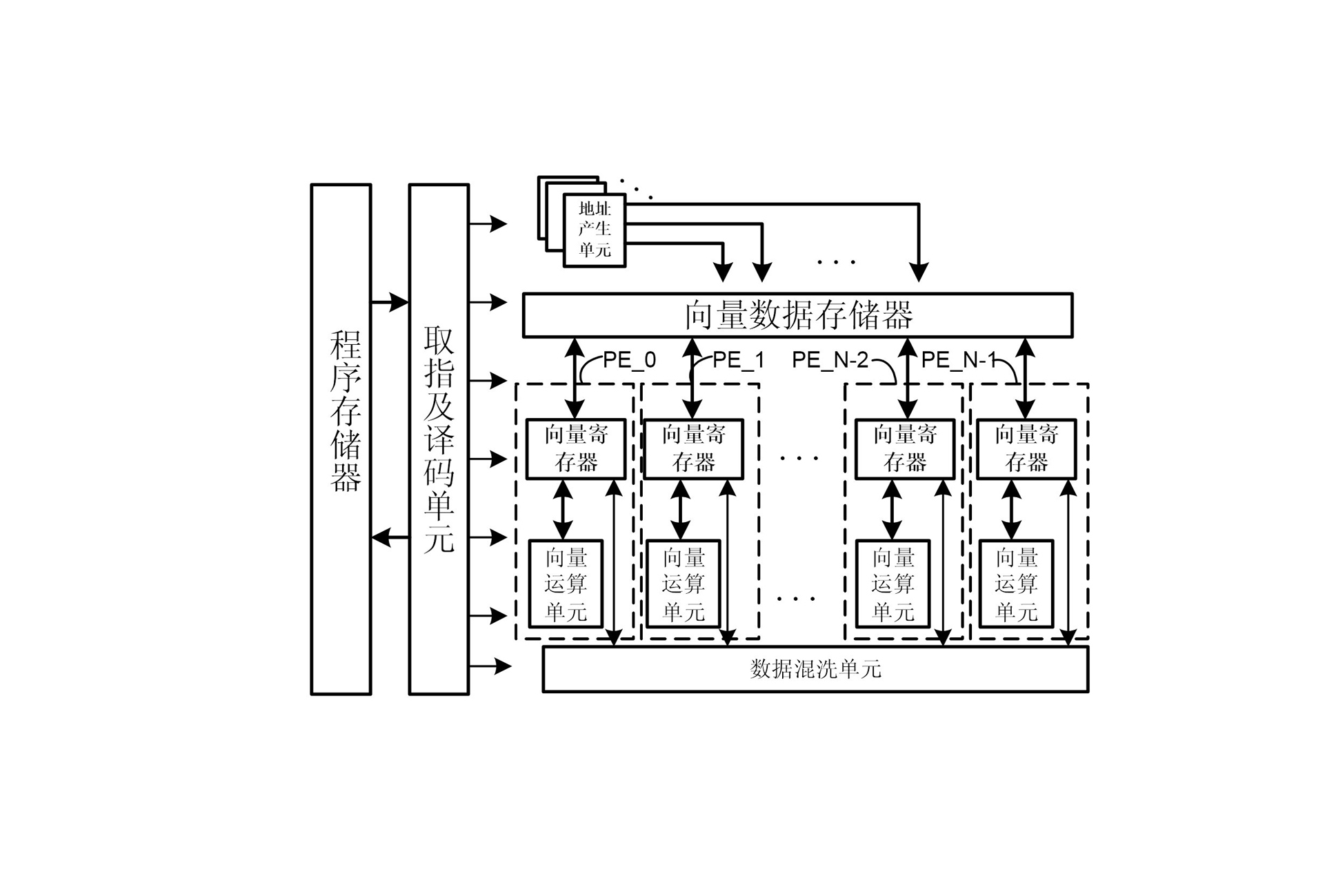
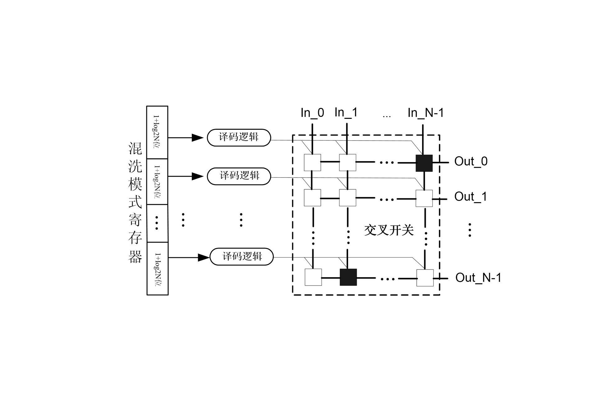
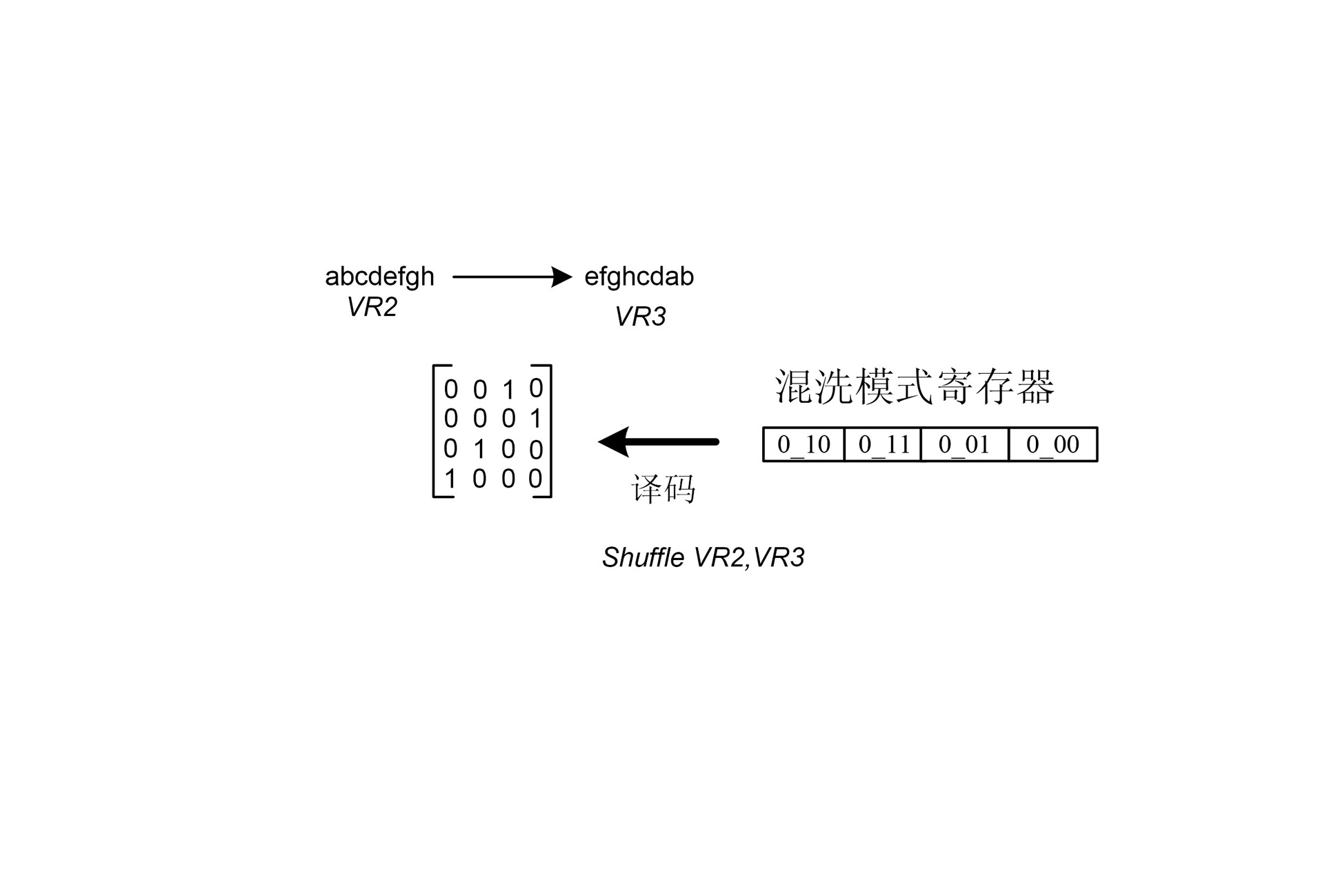
[0033] Such as Figure 4 As shown, the data shuffling unit with switch matrix memory of the present invention includes a crossbar, an input logic unit that controls the crossbar to input data from the vector register, and an output logic unit that controls the crossbar output data to the vector register, and data shuffling The unit also includes a main control logic unit connected to the vector register for controlling conversion of the shuffling request and performing a shuffling operation, and a switch matrix memory connected to the main control logic unit for storing the conversion result of the shuffling request, the main control logic The unit is connected to the input logic unit and controls the source operand vector to be shuffled from the input logic unit to the crossbar, and the crossbar is controlled by the switch matrix mem...


PUM


Abstract

The invention discloses a data shuffling unit with a switch matrix memory, comprising a crossbar switch, an input logic unit, an output logic unit, a main control logic unit and a switch matrix memory, wherein the main logic unit is connected with the input logic unit, and the output end of the switch matrix memory is connected with a switch selection signal end of the crossbar switch. The invention also provides a shuffling method of the data shuffling unit, when pretreatment is carried out, a shuffling request in a user program is converted into a switch matrix in the switch matrix memory, and when a shuffling instruction is executed, the main control logic unit controls to read a switch matrix corresponding to a required shuffling mode from the switch matrix memory and then further controls the crossbar switch directly to carry out data selection recombination. The data shuffling unit has the characteristics of simple structure, flexibility and high efficiency in shuffling, short time delay of key circuits and suitability for any shuffling operation.

Description

technical field [0001] The invention relates to the field of digital signal processors of SIMD technology, in particular to a data shuffling unit and a shuffling method thereof. Background technique [0002] SIMD (Single Instruction Stream Multiple Data streams) technology generally includes sub-word parallel technology and vector technology, both of which develop data-level parallelism of applications from both micro and macro directions. SIMD technology can process multiple parallel data while executing one instruction, and its high power efficiency has great advantages in solving computing-intensive applications, so it has been widely used and developed, and is favored by processors, especially DSP (Digital Signal Processor, Digital Signal Processor) of all ages. figure 1 It is a schematic diagram of a typical DSP structure using SIMD technology, which is represented by figure 1 It can be seen that the instruction fetching and decoding unit reads instructions from the p...

Claims


Application Information

Patent Timeline
Patent Type & Authority Applications(China)
IPC IPC(8): G06F9/30
Inventor 陈书明刘胜万江华陈海燕陈跃跃孙永节彭元喜杨惠刘祥远李振涛
Owner NAT UNIV OF DEFENSE TECH
Why Eureka
Try Eureka