
Non-core layer package substrate and manufacturing method thereof

A core-less, packaged substrate technology, applied in semiconductor/solid-state device manufacturing, electrical components, electrical solid-state devices, etc., can solve problems such as poor coplanarity, difficult tolerance control of volume and height, and damage to semiconductor chip contacts.

Active Publication Date: 2011-05-11
UNIMICRON TECH CORP
View PDF0 Cites 15 Cited by
  • Summary
  • Abstract
  • Description
  • Claims
  • Application Information

AI Technical Summary

Problems solved by technology

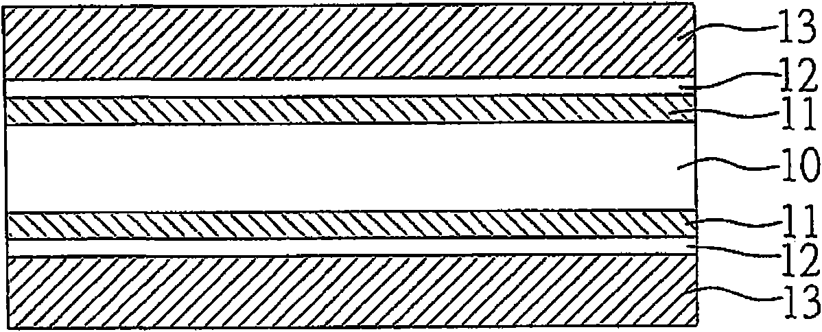
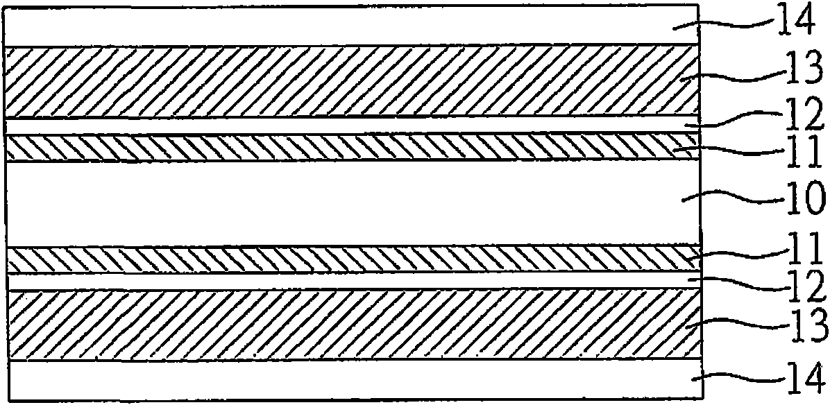
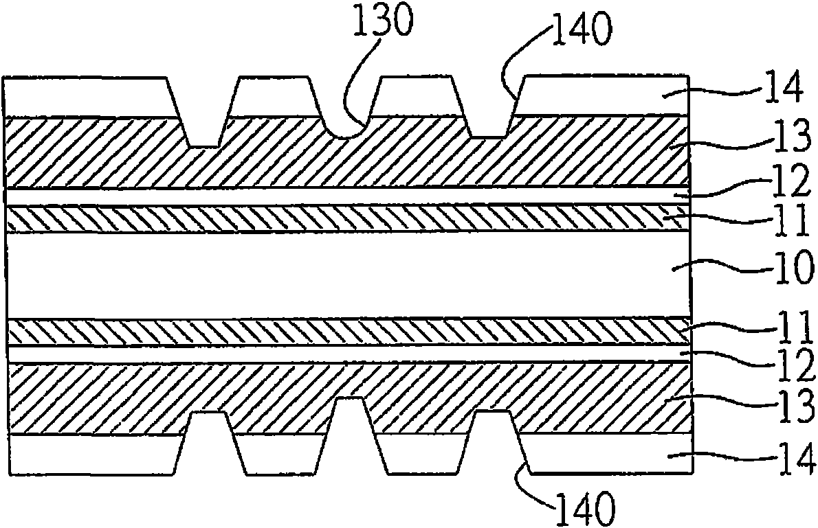
[0012] However, in the existing manufacturing method, because the bearing metal layer 13 is a metal material, the depression 130 can only be formed on the bearing metal layer 13 by etching, and its aperture and depth have certain tolerances, which will lead to subsequent formation of the depression 130. The tolerance control of the volume and height of each of the solder bumps 141a in the recess 130 is not easy, so that the coplanarity (coplanarity) is poor, which will easily cause the semiconductor chip contact to be damaged due to stress (stress) imbalance, or the semiconductor chip Part of the electrode pads of the chip fail to form a contact with the corresponding solder bump 141a due to insufficient height, resulting in an invalid electrical connection; moreover, if the average volume or height of the solder bump 141a When it is too high, when the reflow manufacturing method is carried out, the solder bump 141a will be prone to the phenomenon of contact bridging (bridge) that causes a short circuit due to deformation.
[0013] Therefore, in view of the above-mentioned problems, how to avoid many problems that are not conducive to the design of fine pitch caused by the manufacturing method of the core-less packaging substrate in the prior art has become an urgent problem to be solved at present.

Method used


Image

  • Non-core layer package substrate and manufacturing method thereof
  • Non-core layer package substrate and manufacturing method thereof
  • Non-core layer package substrate and manufacturing method thereof

Examples


Embodiment Construction

[0071] The following describes the implementation of the present invention through specific specific examples. Those skilled in the art can easily understand other advantages and effects of the present invention from the content disclosed in this specification.

[0072] See Figure 2A to 2K , Is a method for manufacturing a core-less packaging substrate disclosed in the present invention.

[0073] Such as Figure 2A As shown, a substrate 2a is provided, which is composed of a carrier layer 20 having opposite surfaces, a release film 21 partially formed on the opposite surfaces of the carrier layer 20, and an adhesive layer 20a surrounding the area outside the release film 21 , The metal layer 22 formed on the release film 21 and the adhesion layer 20a, a first resist layer 23a formed on the metal layer 22, and an auxiliary dielectric layer 24 formed on the first resist layer 23a , And an effective area A is defined on each auxiliary dielectric layer 24; wherein the area of ​​the ca...


PUM


Abstract

The invention provides a non-core layer package substrate and a manufacturing method thereof. The non-core layer package substrate comprises a substrate body and a plurality of electrical contact lugs, wherein the substrate body is composed of an auxiliary dielectric layer, a lining circuit and a layer-adding structure; the auxiliary dielectric layer is provided with a first surface and a second surface which are opposite to each other; the lining circuit is arranged on the second surface; the layer-adding structure is arranged on the second surface and the lining circuit; each electrical contact lug is composed of a metal post and a solder layer; the metal post is provided with a first end and a second end which are opposite to each other; the solder layer is arranged on the first end; the second end of the metal post is arranged in the auxiliary dielectric layer and electrically connected with the lining circuit; and the first end of the metal post and the solder layer protrude on the first surface of the auxiliary dielectric layer, thus obtaining electrical contact lugs with superfine pitch and even height. By forming small-bore open pores which pass through the auxiliary dielectric layer and a first barrier layer, the non-core layer package substrate can effectively control the average value and allowance of volume and height of the electrical contact lugs formed in open pores, thereby obtaining the lugs with superfine pitch.

Description

Technical field [0001] The invention relates to a core-less packaging substrate and a manufacturing method thereof, in particular to a core-less packaging substrate with ultra-fine line spacing and a manufacturing method thereof. Background technique [0002] With the vigorous development of the electronics industry, electronic products are gradually moving towards the trend of multi-function and high performance. In order to meet the packaging requirements of high integration and miniaturization of semiconductor packages for more active passive components and circuit loading, semiconductor packaging substrates have gradually evolved from double-layer circuit boards to multilayer circuits Multi-layer board, which uses interlayer connection in a limited space to expand the available circuit layout area on the semiconductor package substrate to meet the needs of high-density integrated circuits , And reduce the thickness of the package substrate, which can achieve the purpose of l...

Claims


Application Information

Patent Timeline
Patent Type & Authority Applications(China)
IPC IPC(8): H01L23/498H01L23/488H01L23/13H01L21/48
CPCH01L2924/0002
Inventor 许诗滨
Owner UNIMICRON TECH CORP
Learn More