
High-accuracy railhead forging hydraulic machine

A hydraulic press, high-precision technology, applied in the direction of forging/pressing/hammering machinery, forging/pressing/hammer devices, manufacturing tools, etc., can solve the problems of long waiting time, energy waste, low efficiency, etc., and achieve high precision The effect of suppressing, meeting manufacturing needs, and improving production efficiency

Active Publication Date: 2011-05-18
TIANJIN TIANDUAN PRESS CO LTD
View PDF4 Cites 16 Cited by
  • Summary
  • Abstract
  • Description
  • Claims
  • Application Information

AI Technical Summary

Problems solved by technology

[0002] At present, the equipment used for rail head pressing and forming mainly adopts three-beam and four-column hydraulic presses, and the pressing and forming is a hot-mould pressing process with one mold, front and rear double stations. According to the characteristics of raw materials, product shape characteristics or differences in production processes, the The raw materials are pressed many times. The disadvantage of the traditional rail head pressing equipment is that the upper and lower sequences of the equipment are completed manually with the crane, the efficiency is low, the mold is difficult to match, the precision of the pressed workpiece is not high, the labor intensity of the workers is high, and the waiting time is high. long, and the waste of energy is serious. With the emergence of high-speed trains, the demand for rails is increasing, and the quality and precision required are also getting higher and higher. The traditional one-mold front and rear double-station pressing hydraulic press can no longer meet the high precision requirements. Rail Head Manufacturing Requirements

Method used


Image

  • High-accuracy railhead forging hydraulic machine
  • High-accuracy railhead forging hydraulic machine
  • High-accuracy railhead forging hydraulic machine

Examples


Embodiment Construction

[0023] In order to further understand the invention content, characteristics and effects of the present invention, the following examples are given, and detailed descriptions are as follows in conjunction with the accompanying drawings:

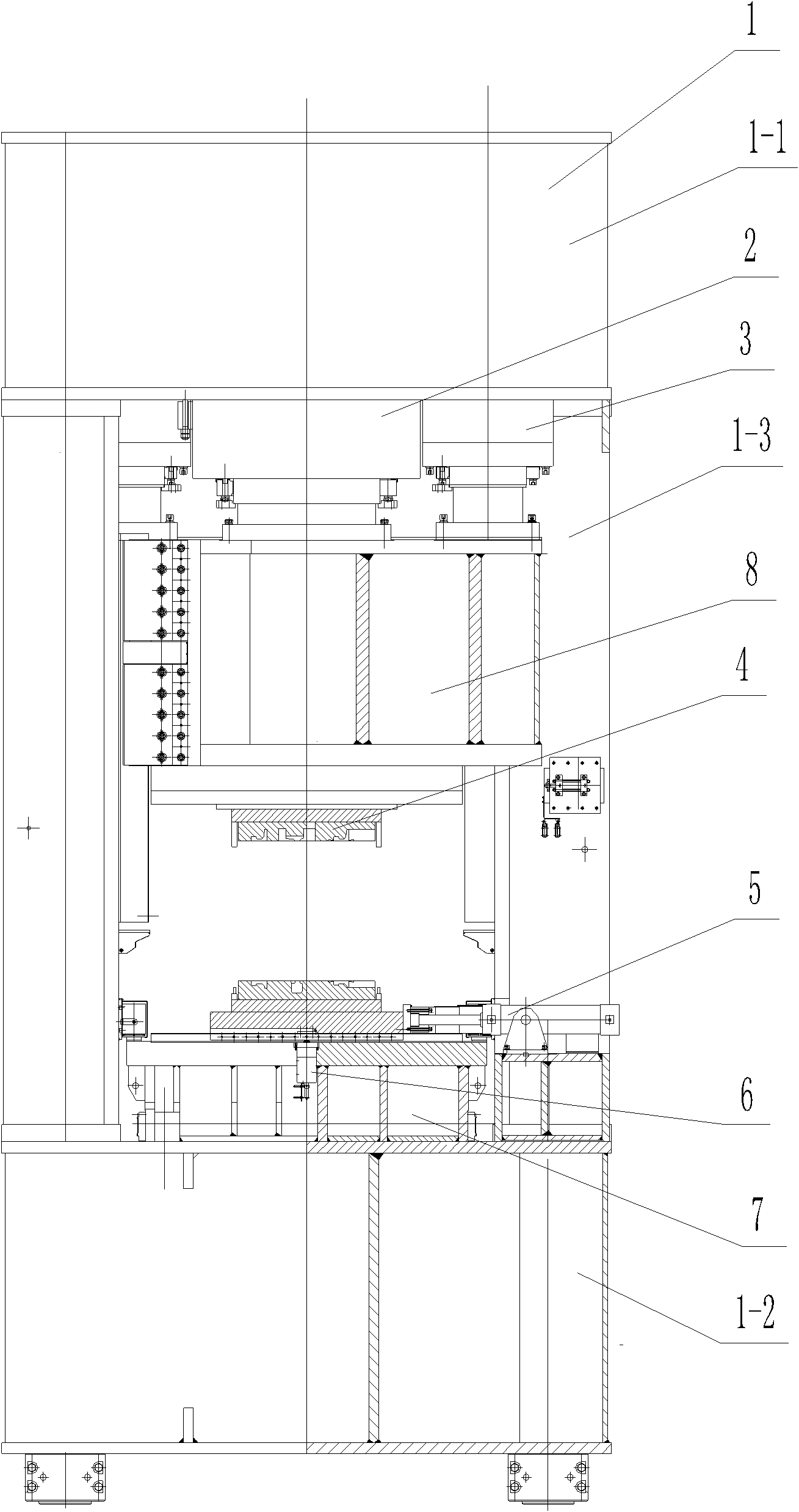
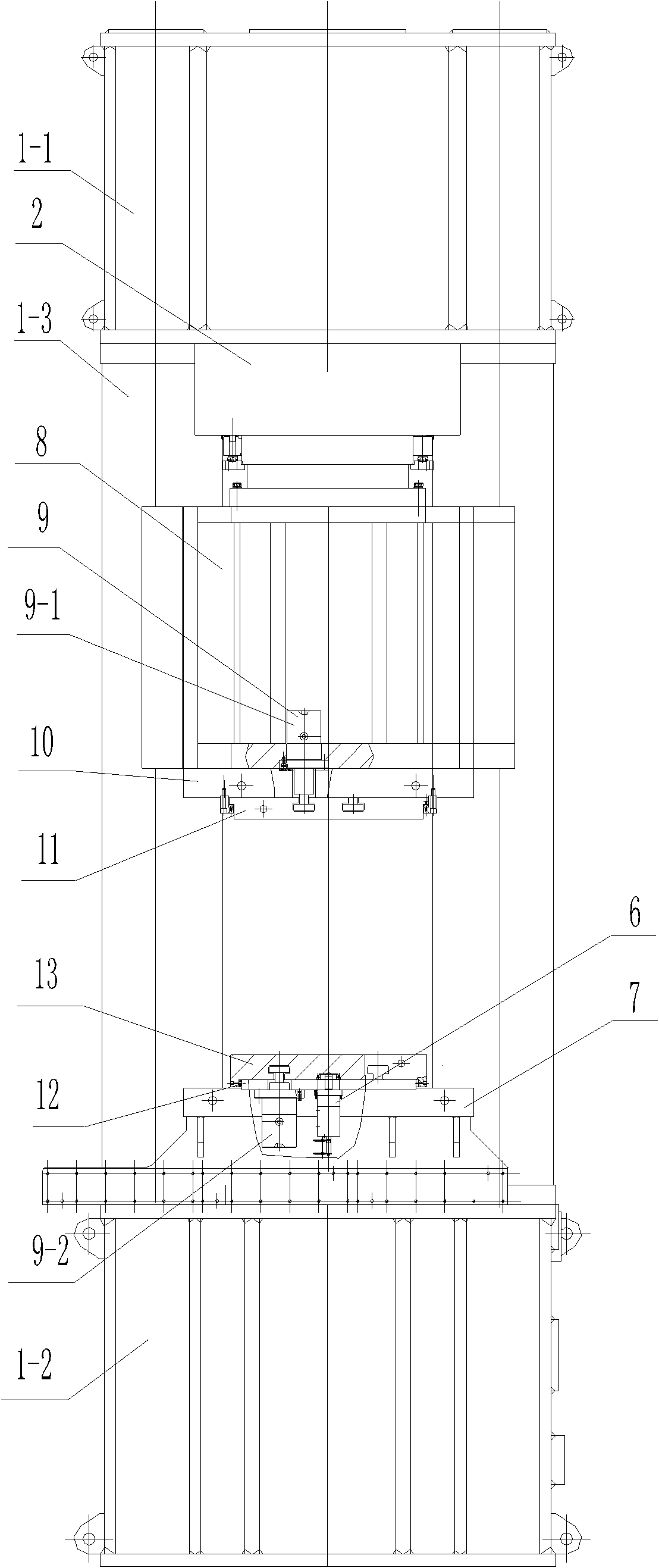
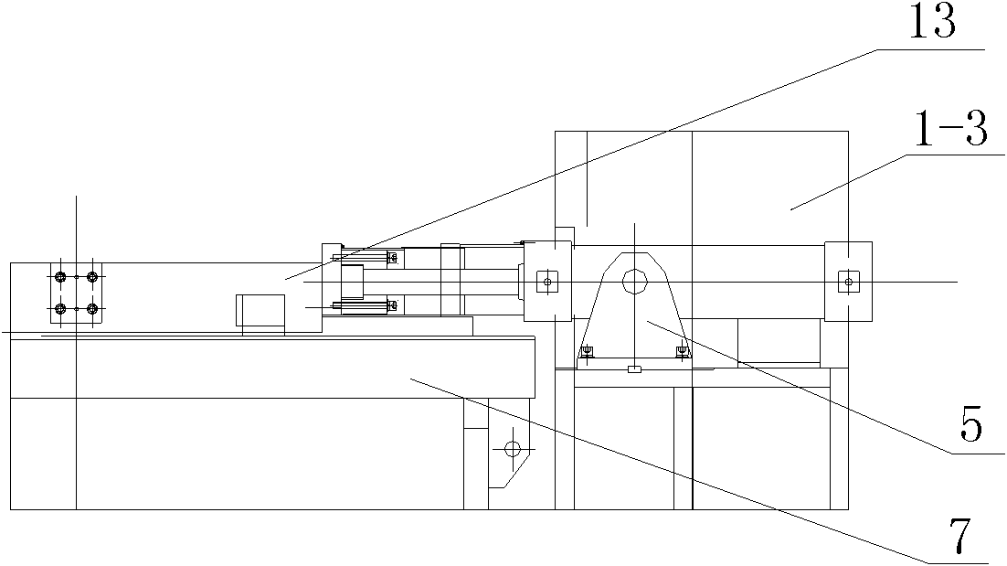
[0024] see Figure 1-Figure 5 , a high-precision rail head forging hydraulic machine, including a combined frame body 1 composed of an upper beam 1-1, a lower beam 1-2 and four columns 1-3, a main cylinder 2 and a side cylinder 3 fixed on the upper beam , the slide block 8 connected with the main cylinder and the side cylinder and the mobile workbench 7 installed on the lower beam. The bottom of the slider 8 is equipped with an upper backing plate 10 and an upper sliding plate 11, and the upper sliding plate is formed with a T-shaped groove matching the T-shaped head of the piston rod of the upper clamping cylinder, and the upper clamping cylinder 9 passes through the upper pad The plate 10 fastens the upper slide plate 11 and the slider. T...


PUM


Abstract

The invention relates to a high-accuracy railhead forging hydraulic machine which comprises a combined frame type machine body, a main cylinder, a side cylinder, a sliding block and a movable work table, wherein the combined frame type machine body consists of an upper beam, a lower beam and four upright posts, and the sliding block is connected with the main cylinder and the side cylinder. The high-accuracy railhead forging hydraulic machine is characterized in that an upper cushion plate and an upper sliding plate are arranged at the bottom of the sliding block; the upper sliding plate is fastened with the sliding block through an upper clamping cylinder; a lower cushion plate and a lower sliding plate are arranged on the movable work table; the lower sliding plate is tightly clamped with the movable work table through the lower clamping cylinder, wherein a mould pushing device is arranged between two upright posts at one side, and a mould positioning device is arranged in the middle of the movable work table. The invention has the advantages that the hydraulic machine is not only suitable for the hot compression molding process of an AT rail heel-end, but also applied to the pressing forming process of plasticity materials according to demands. Because the accuracy retentivity of the heated and pressed high-accuracy railhead forging hydraulic machine is good, the mould pushing device and the mould positioning device can not only realize multi-station pressing and accurate positioning in the multi-station pressing process, and can ensure the high-accuracy pressing of workpieces.

Description

technical field [0001] The invention belongs to forging equipment, in particular to a high-precision rail head forging hydraulic machine. Background technique [0002] At present, the equipment used for rail head pressing and forming mainly adopts three-beam and four-column hydraulic presses, and the pressing and forming is a hot-mould pressing process with one mold, front and rear double stations. According to the characteristics of raw materials, product shape characteristics or differences in production processes, the The raw materials are pressed many times. The disadvantage of the traditional rail head pressing equipment is that the upper and lower sequences of the equipment are completed manually with the crane, the efficiency is low, the mold is difficult to match, the precision of the pressed workpiece is not high, the labor intensity of the workers is high, and the waiting time is high. long, and the waste of energy is serious. With the emergence of high-speed train...

Claims


Application Information

Patent Timeline
IPC IPC(8): B21K7/10B21J13/08
Inventor 王鑫
Owner TIANJIN TIANDUAN PRESS CO LTD
Learn More