Numerically controlled turning-grinding combined machine tool

A compound machine tool, turning and grinding technology, applied in the field of CNC machine tools, can solve the problems of large cumulative error in machining accuracy of camshaft parts, long machining cycle, insufficient rigidity, etc., and achieve machining accuracy guarantee, reliable machining accuracy, rigidity and stability. Effect

Inactive Publication Date: 2011-05-18
张家口万全区京仪机床有限公司
View PDF7 Cites 7 Cited by
  • Summary
  • Abstract
  • Description
  • Claims
  • Application Information

AI Technical Summary

Problems solved by technology

[0003] At present, domestically produced camshafts need to be roughly machined on a lathe first, then grind the position where the bearing is installed on a cylindrical grinder, and finally grind the cam position of the camshaft on a camshaft grinder; due to the processing of the camshaft It needs to be carried out on various machine tools through multiple processes, and the workpiece must be re-clamped in each process. Therefore, the cumulative error of the machining accuracy of the camshaft parts is large and the processing cycle is long.
[0004] The domestic CNC camshaft grinding machines used by domestic camshaft manufacturers and most of the imported CNC camshaft grinding machines mainly adopt a T-shaped structure. The X-direction movement, the worktable drives the spindle unit to move in the Z-direction; this structure is only suitable for fine grinding and light-load grinding of the cam part of the camshaft, and the parts can still be guaranteed when working with low load and unidirectional cutting force. However, it is not s

Method used


Image

  • Numerically controlled turning-grinding combined machine tool
  • Numerically controlled turning-grinding combined machine tool
  • Numerically controlled turning-grinding combined machine tool

Examples


Example Embodiment

[0029] In order to have a clearer understanding of the technical features, objectives and effects of the present invention, specific embodiments of the present invention will now be described with reference to the accompanying drawings.

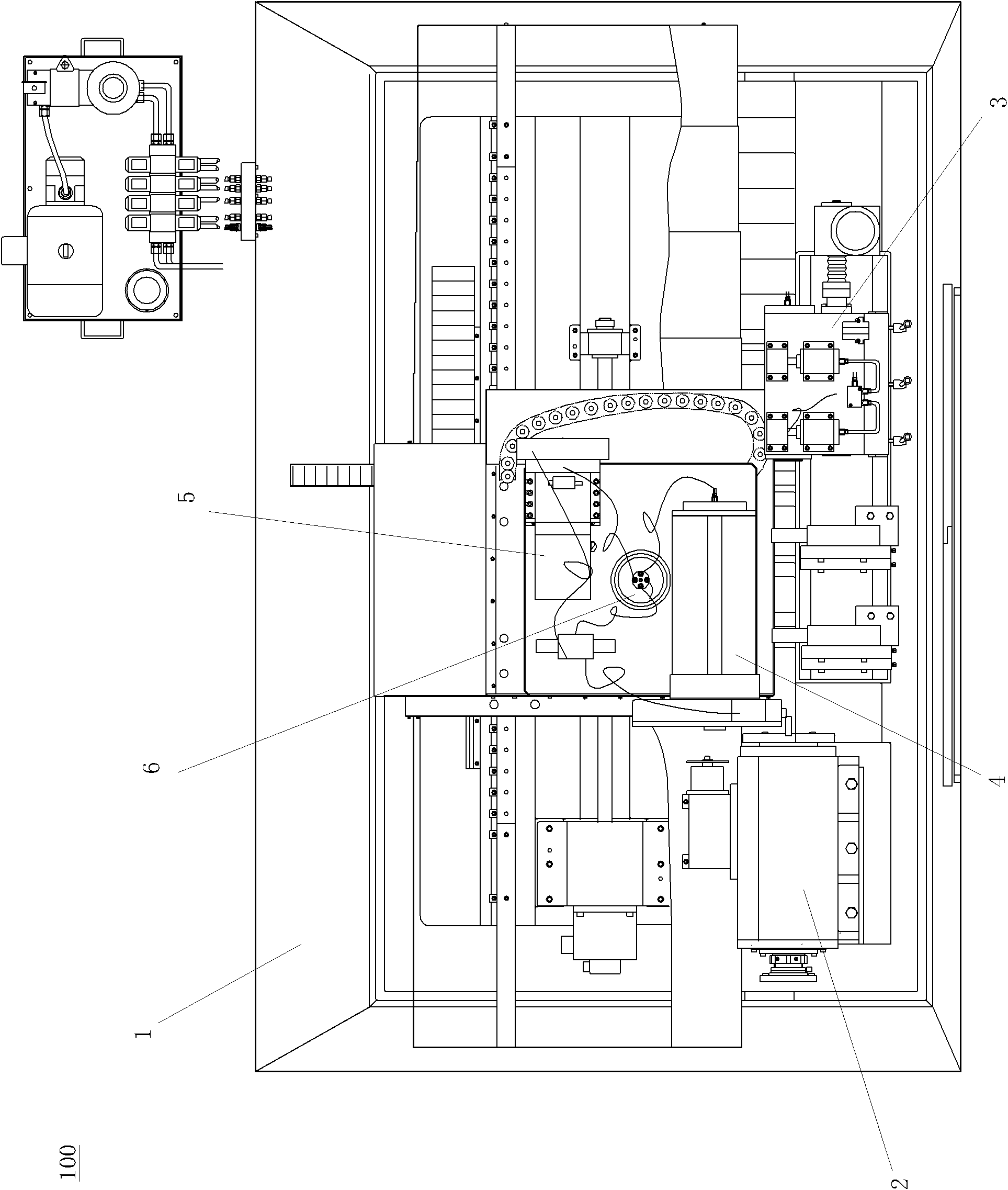
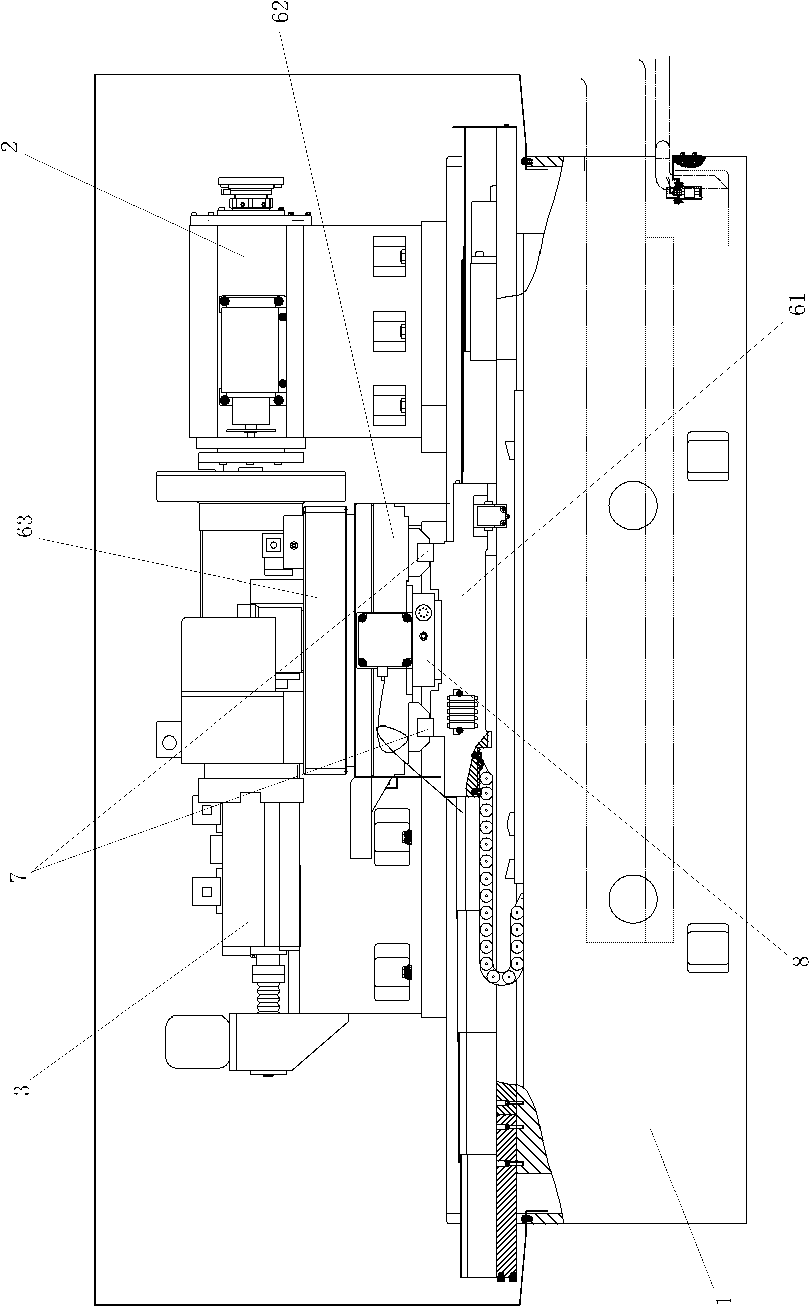
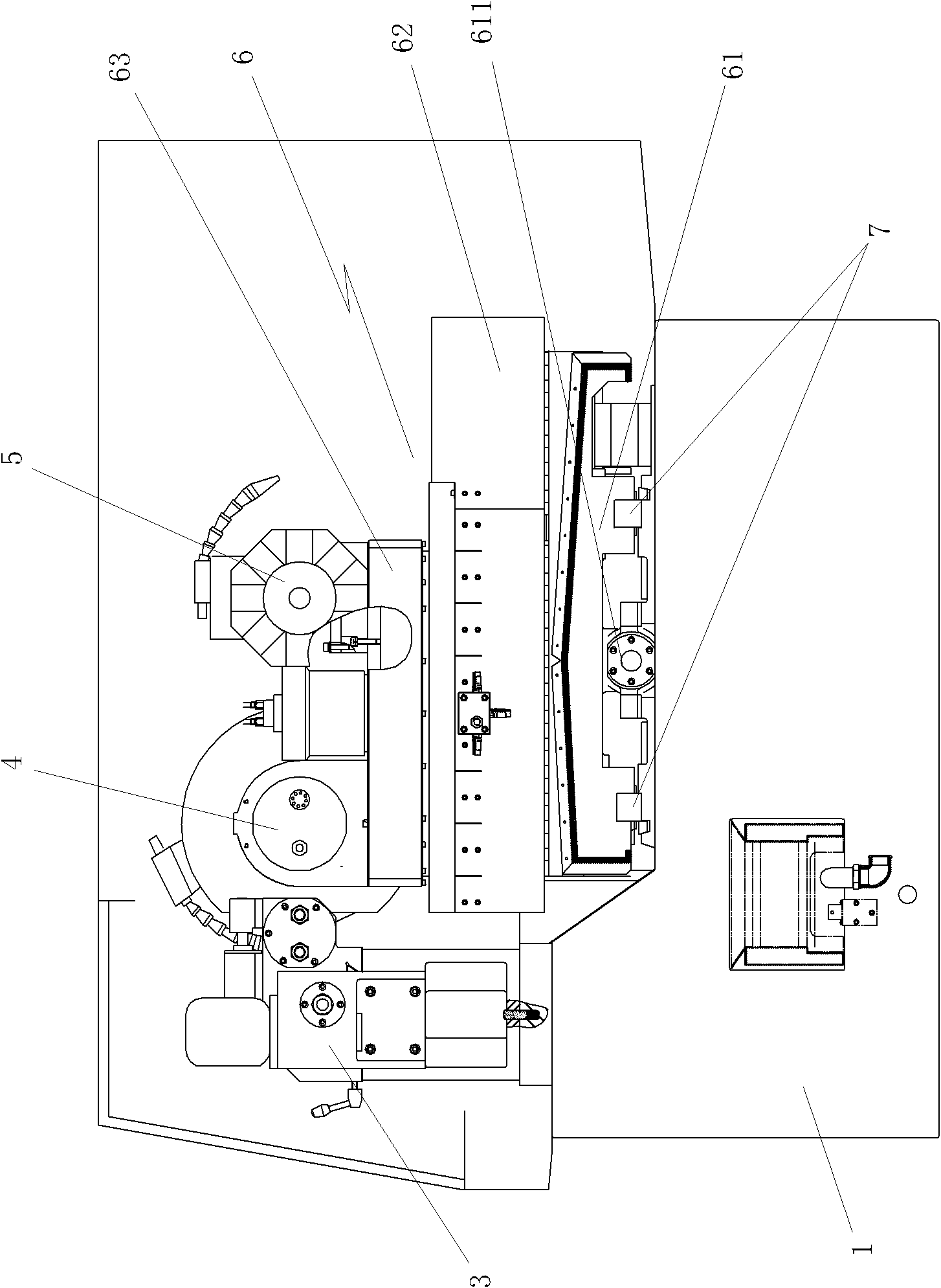
[0030] Such as Figure 1 ~ Figure 4 As shown, the present invention provides a numerical control lathe-grinding compound machine tool 100. A spindle part 2 and a tailstock 3 corresponding to the spindle part are provided on one side of the upper surface of a rectangular bed 1, and the other side of the rectangular bed 1 is provided The workbench 6 supporting the grinding wheel holder 4 and the turning tool holder 5; Figure 5 As shown, the spindle component 2 is composed of a spindle base 22 and a servo electric spindle 21 arranged on the base. The front of the servo electric spindle is provided with a clamping part (not shown in the figure) for mounting a workpiece. Such as figure 2 , image 3 with Figure 4 As shown, the workbench 6 includes ...


PUM


Abstract

The invention relates to a numerically controlled turning-grinding combined machine tool. One side of the upper surface of a rectangular machine tool body is provided with a spindle component and a tail seat corresponding to the spindle component, and the other side of the machine tool body is provided with a worktable supporting a grinding wheel frame and a turning tool frame; the spindle component comprises a spindle base and a servo electric spindle arranged on the base; the worktable comprises a first worktable and a second worktable, wherein the first worktable parallelly moves in an axial direction with the electric spindle; the second worktable moving in a direction vertical to the moving direction of the first worktable is arranged above the first worktable; a horizontal rotation worktable is arranged above the second worktable; one side of the horizontal rotation worktable is provided with a grinding wheel frame, and the other side of the horizontal rotation worktable is provided with a turning tool frame; the bottoms of the first worktable and the second worktable are both provided with rolling heavy-load linear guide rail pairs; and the bottom of the second worktable is provided with a linear motor driving the second worktable to move. The rigidity and stability of the entire structure of the combined machine tool are greatly improved, the processing precision is reliably ensured, and high-precision manufacturing of cam shaft processing is realized.

Description

technical field [0001] The invention relates to a numerical control machine tool, in particular to a numerical control turning and grinding compound machine tool for turning and grinding long shaft parts. Background technique [0002] With the rapid development of my country's automobile manufacturing industry, in order to meet the continuous improvement of the quality requirements of the camshaft in the engine manufacturing field and the increasing speed of replacement, especially the cold shock casting camshaft (the cold shock casting camshaft is a kind of parts rough After the technology of castings whose hardness meets the hardness requirements of the finished camshaft has been widely used in the engine manufacturing industry, the demand for powerful cutting equipment in the domestic market is more urgent. [0003] At present, domestically produced camshafts need to be roughly machined on a lathe first, then grind the position where the bearing is installed on a cylindric...

Claims


Application Information

Patent Timeline
IPC IPC(8): B23P23/02
Inventor 薛鹏祥
Owner 张家口万全区京仪机床有限公司
Why Eureka
Try Eureka