
Boring cutter with through groove for machining conduit hole

A technology of conduit holes and through grooves, which is applied in metal processing equipment, tools for lathes, manufacturing tools, etc., can solve the problems of low service life of cemented carbide materials, low machining accuracy and cutting speed, and insufficient strength of polycrystalline diamond. problems, to achieve the effect of good thermal conductivity and wear resistance, enhanced stability, and conducive to high-speed and high-precision processing

Inactive Publication Date: 2011-05-25
ZHENGZHOU DIAMOND PRECISION MFG
View PDF7 Cites 0 Cited by
  • Summary
  • Abstract
  • Description
  • Claims
  • Application Information

AI Technical Summary

Problems solved by technology

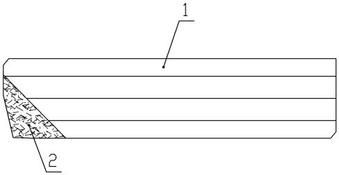
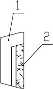
like figure 1 , figure 2 and image 3 As shown, the existing through-slot boring tool for machining conduit holes includes a cutter body 1 and a cutting part 2 welded on the upper surface of the front end of the cutter body 1. The cutting part 2 is made of solid carbide or polycrystalline diamond (PCD) Among them, the range of carbide processing materials is limited and the processing accuracy and cutting speed are too low. The service life of cemented carbide materials is low and the processing efficiency is low. Polycrystalline diamond (PCD) materials can achieve high-speed and high-precision processing, but it will Due to the welding instability in the welding process, the cutting strength of polycrystalline diamond (PCD) is not enough, the stability is poor, and the service life is reduced
In addition, the surface of the cutter body 1 is horizontal and smooth, and the tightness between the pressure plate on the machine tool and the cutter body is not high. During processing, the part size error or the surface processing accuracy will be reduced due to the unstable clamping of the cutter body.

Method used


Image

  • Boring cutter with through groove for machining conduit hole
  • Boring cutter with through groove for machining conduit hole
  • Boring cutter with through groove for machining conduit hole

Examples


Embodiment Construction

[0015] like Figure 4 ~ Figure 6 As shown, the through-groove boring tool for processing conduit holes of the present invention includes a cutter body 1, the upper surface of the cutter body 1 is provided with a cutting part 2 that fully covers the upper surface of the cutter body 1, and the cutter body 1 and the cutting part 2 are integrated by welding In this way, the joint surface between the cutting part 2 and the cutter body 1 is increased, the strength of the cutting part 2 is increased, and the stability is enhanced; the two ends of the cutting part 2 are respectively provided with a cutting edge 4 and a cutting edge 5, so that the front and rear of the boring tool The cutting edge 4 and the cutting edge 5 can be exchanged for use, which greatly prolongs the service life of the present invention. The cutting part 2 is made of polycrystalline diamond (PCD), which can achieve high machining accuracy in high-speed cutting, and the cutting part 2 made of PCD can also proces...


PUM


Abstract

The invention discloses a boring cutter with a through groove for machining a conduit hole. The cutter comprises a cutter body, wherein the upper surface of the cutter body is provided with a cutting part which totally covers the upper surface of the cutter body; two ends of the cutting part are provided with a cutting blade respectively; the cutting part is made of polycrystalline diamond; a through groove is formed in the middle of the surface of the cutting part along the length direction by employing laser technology; and the surface of the cutting part is subjected to machining of roughness and dimensional accuracy by employing the laser technology. The cutting part is totally arranged on the surface of the cutter body, the joint surface of the cutting part and the cutter body is enlarged, so the strength of the cutting part is improved, and the stability is improved; moreover, two ends of the cutting part are provided with a cutting blade respectively, so the cutting blade at two front and rear ends of the boring cutter can be exchanged, and the service life of the boring cutter is greatly prolonged.

Description

technical field [0001] The invention belongs to the technical field of machining and manufacturing, and in particular relates to a through-slot boring tool for machining catheter holes. Background technique [0002] At present, the machining tools used to process the conduit hole of the cylinder head of the automobile engine adopt a multi-blade compound (knife-edge machine clamp, inlaid welding combination) structure, and use reaming, boring, and extrusion instead of grinding. Since the conduit hole belongs to deep hole processing, The requirements for dimensional accuracy and surface roughness are relatively high. In the application of the conduit hole processing of the engine cylinder head, the machining accuracy and surface quality of the precision boring tool are better than that of the gun reamer. like figure 1 , figure 2 and image 3 As shown, the existing through-slot boring tool for machining conduit holes includes a cutter body 1 and a cutting part 2 welded on ...

Claims


Application Information

Patent Timeline
Patent Type & Authority Applications(China)
IPC IPC(8): B23B27/00B23B27/14
Inventor 张伟峰张海斌
Owner ZHENGZHOU DIAMOND PRECISION MFG
Learn More