Numerical control machining clamping method for aircraft wing beam parts

A technology of parts and clamping, which is applied in the field of high-efficiency CNC machining of aircraft wing beam parts, can solve the problems of no longer practical processing methods, difficult clamping and positioning, and long time required for clamping and positioning of parts, so as to save preparation time, avoid secondary correction errors, design and manufacture simple effects

Active Publication Date: 2011-05-25
XIAN AIRCRAFT IND GROUP
View PDF0 Cites 10 Cited by
  • Summary
  • Abstract
  • Description
  • Claims
  • Application Information

AI Technical Summary

Problems solved by technology

With the development of domestic aviation technology, aircraft are becoming larger and larger, and the structure of beam parts is becoming more and more complex. The size of parts and the weight of blanks are getting larger and larger, often more than ten meters long and several tons in weight. Clamping and positioning are carried out during the processing It is getting more and more difficult, the time required to set up and position the part is getting longer and longer, and the usual processing methods are no longer practical

Method used


Image

  • Numerical control machining clamping method for aircraft wing beam parts
  • Numerical control machining clamping method for aircraft wing beam parts
  • Numerical control machining clamping method for aircraft wing beam parts

Examples


Embodiment Construction

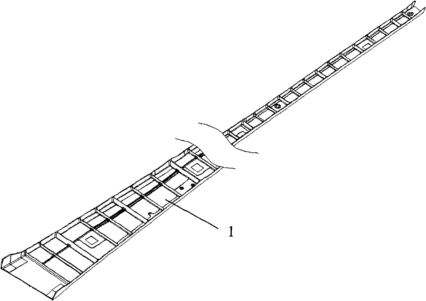
[0014] figure 1 The beam part 1 shown is a complex elongated structure, the bottom is flat, and the height of the rib top of the part varies unevenly.

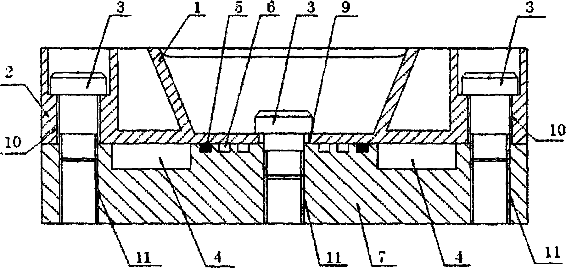
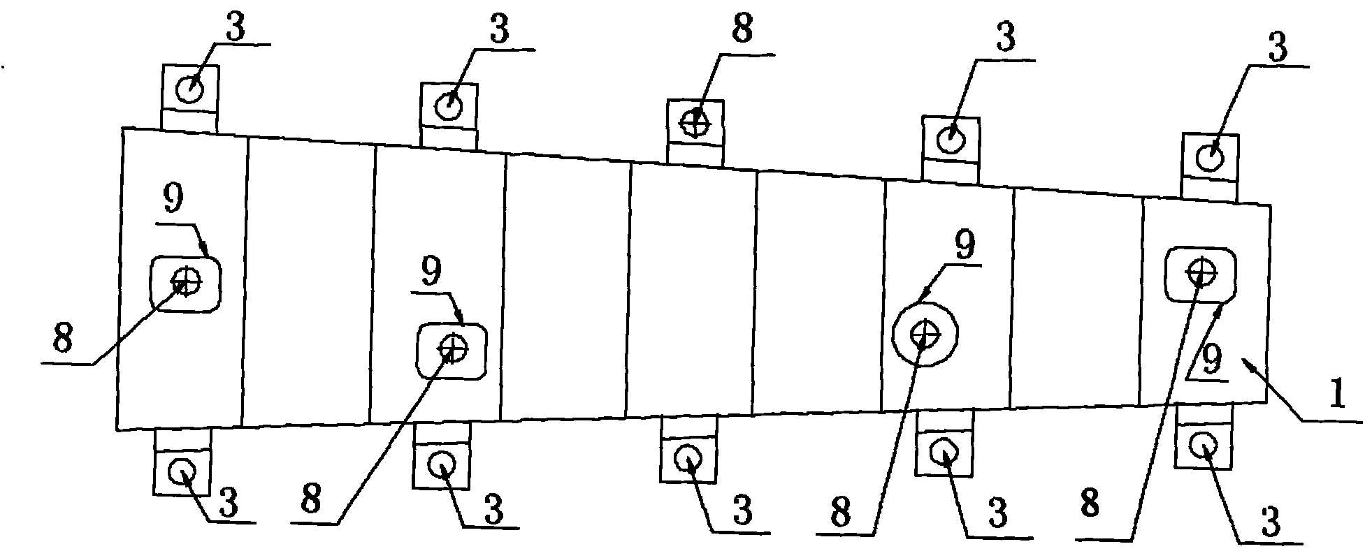
[0015] figure 2 The beam part 1 shown is clamped on the vacuum milling body 7, and the undercut 4 of the closed angle of the machining shape of the part on both sides of the tool is milled at the theoretical shape position of the part 1. The theoretical outline of the part is located in the undercut of the milling tool. The width of the undercut 4 is preferably 1.5-2 times the diameter of the tool used to process the shape of the part. The depth of the undercut should be based on the diameter of the tool used and the shape of the part. The size of the web angle is considered comprehensively. Take the tool whose diameter is D and the bottom angle is R0 as an example. If the closed angle of the part is α, then the depth H of the undercut should be greater than D*sinα / tgα. On both sides of the blank of the part 1, a number of...


PUM


Abstract

The invention discloses a numerical control machining clamping method for large-scale beam parts. The method comprises the following steps of: on the basis of theoretical appearances of parts, machining a plurality of positioning process platforms and compression process platforms on a blank; machining positioning holes and compression holes on a milling tool correspondingly; reserving a tool withdraw groove on the milling tool; and positioning the part blank in the positioning holes on the milling tool through the positioning process platforms and compressing and fixing in the compression holes of the milling tool through the compression process platforms. The overall appearance is machined in place by a tool through one-time clamping; the preparation time is saved; a secondary alignment error is avoided; therefore, the numerical control machining efficiency and the quality are improved; and the milling tool is simple to design and manufacture.

Description

technical field [0001] The invention relates to the technical field of aircraft manufacturing, in particular to a clamping method used in high-efficiency numerical control machining of aircraft wing beam parts. Background technique [0002] At present, with the rapid development of CNC machining technology and aircraft design technology, many parts on the aircraft that were originally assembled together by sheet metal riveting are gradually designed into integrated single CNC machining parts. The structure of these individual parts is becoming more and more complex. getting bigger. [0003] The aircraft wing beam parts involved in the present invention are the main positioning and connecting force-bearing parts in the aircraft structure. The main structural features are that the width of the parts varies greatly and the triangular structure is relatively long, and the blanks of the parts adopt super-long lengths. Pre-stretched sheet aluminum alloy material. [0004] Usuall...

Claims


Application Information

Patent Timeline
Patent Type & Authority Applications(China)
IPC IPC(8): B23Q3/00B23C3/00
Inventor 郑小伟张文文惠昕贾保国王中胜
Owner XIAN AIRCRAFT IND GROUP
Why Eureka
Try Eureka