Line drive type linkage light ray tracing method and reflective concentration photovoltaic power generation thereof
A line transmission and transmission line technology, applied in the field of solar automatic tracking and concentrated photovoltaics, can solve the problems of solar energy utilization device deflection space limitation, technical difficulty and cost are not practical, water cooling or air cooling effect is limited, etc., to achieve increased tracking stability Performance and wind resistance, ensuring stability and tracking accuracy, avoiding the effect of error and deformation accumulation
- Summary
- Abstract
- Description
- Claims
- Application Information
AI Technical Summary
Problems solved by technology
Method used
Image
Examples
Embodiment 1
[0044] Embodiment 1, half-wheel line transmission tracking and its array series-parallel linkage:
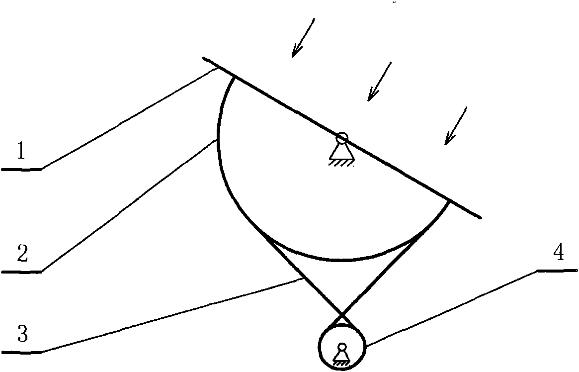
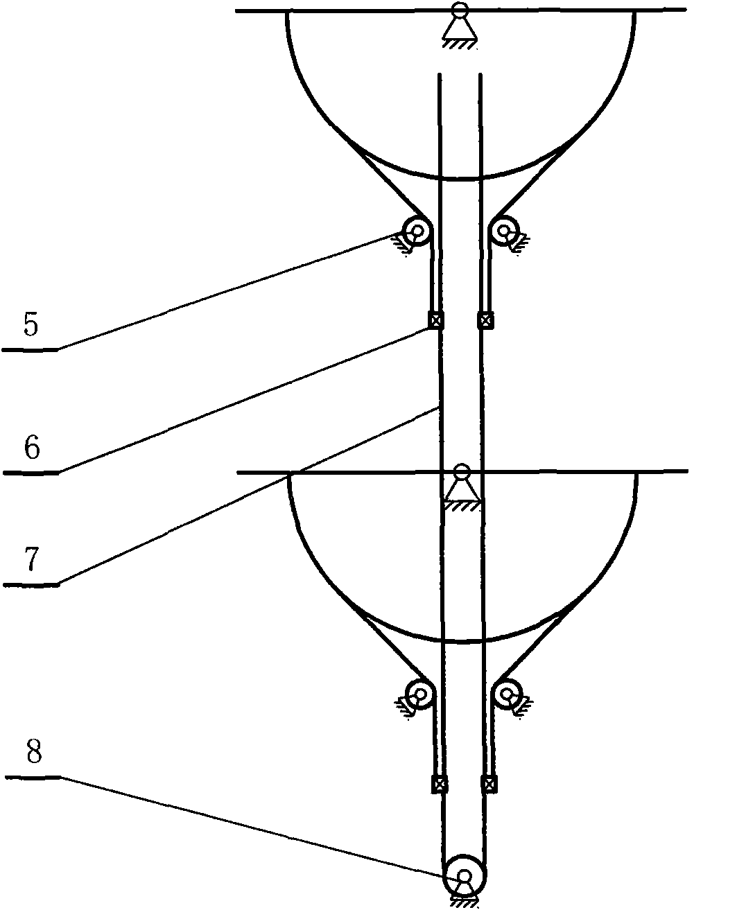
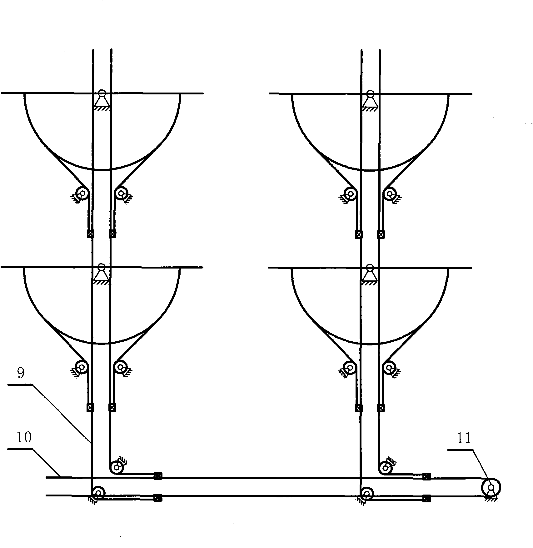
[0045] as attached figure 1 The schematic diagram of a single solar energy utilization device adopts line transmission tracking shown in the figure. The solar energy utilization device 1 is equipped with a large-diameter half wheel 2, and the driving wheel 4 drives the half wheel through the winding transmission of the steel wire rope 3, that is, drags the solar energy utilization device 1 to track. Sunlight is deflected, and the driving wheel 4 and the wound steel wire rope are directly driven by friction force, which is suitable for single-axis tracking of any solar energy utilization device. Because its tracking angle is generally within the range of ±90°, the solar energy utilization device adopts half-wheel transmission, which can increase the diameter of the wheel as much as possible and even exceed the width of the solar energy utilization device, increase the reduction r...
Embodiment 2
[0054] Embodiment 2, vertical pull wire transmission mode:
[0055] In order to further reduce the cost of tracking investment and save half rounds, the following Figure 9 and Figure 10 As shown in the line-driven interlocking tracking method according to the vertical pull drive mode, the solar energy utilization device 20 is dragged by the steel wire rope 21 in the vertical direction and connected to the busbar through the roller guide wheel 22 (the busbar is not shown in the figure). The distance between the steel wire ropes is always changing during this linkage tracking process, and the length of the roller guide wheel must meet the lateral displacement range of the steel wire ropes during the tracking process. It is similar to the connection and transmission mode between the busbars in the tracking array described in Embodiment 1, but in order to adapt to the characteristics of changes in the distance between wire ropes, an additional Figure 11 It shows the double-bu...
Embodiment 3
[0056] Embodiment 3, oblique straight wire transmission mode:
[0057] as attached Figure 12 The line-driven tracking principle of the oblique-straight-pull drive mode shown can avoid the trouble of displacement of the busbar spacing in Embodiment 2. However, a characteristic of the oblique straight-pull transmission method is that with the change of the deflection angle of the solar energy utilization device, the elongation and shortening of the steel wire ropes on both sides vary in different amounts, and a tension compensation device must be added.
[0058] attached Figure 13 is the geometric calculation analysis diagram of the oblique straight pull drive mode, AC is the distance from the action point of the steel wire rope on the solar energy utilization device, AB and BC are the theoretical lengths from the oblique pull length of the steel wire ropes on both sides to the intersection point, O is the deflection center, For the deflection angle of the solar device, set...
PUM
 Abstract
Description
Claims
Application Information
 - R&D
- Intellectual Property
- Life Sciences
- Materials
- Tech Scout
- Unparalleled Data Quality
- Higher Quality Content
- 60% Fewer Hallucinations
Browse by: Latest US Patents, China's latest patents, Technical Efficacy Thesaurus, Application Domain, Technology Topic, Popular Technical Reports.
© 2025 PatSnap. All rights reserved.Legal|Privacy policy|Modern Slavery Act Transparency Statement|Sitemap|About US| Contact US: help@patsnap.com


