Multi-wavelength fiber laser with miniature resonant cavity structures
A fiber laser, resonant cavity technology, applied in lasers, laser parts, phonon exciters, etc., can solve the problems of discontinuous high-quality multi-wavelength laser output, unstable system, low output power, etc., and achieve a simple structure. , the effect of high optical power and narrow frequency band width
- Summary
- Abstract
- Description
- Claims
- Application Information
AI Technical Summary
Problems solved by technology
Method used
Image
Examples
Embodiment approach 1
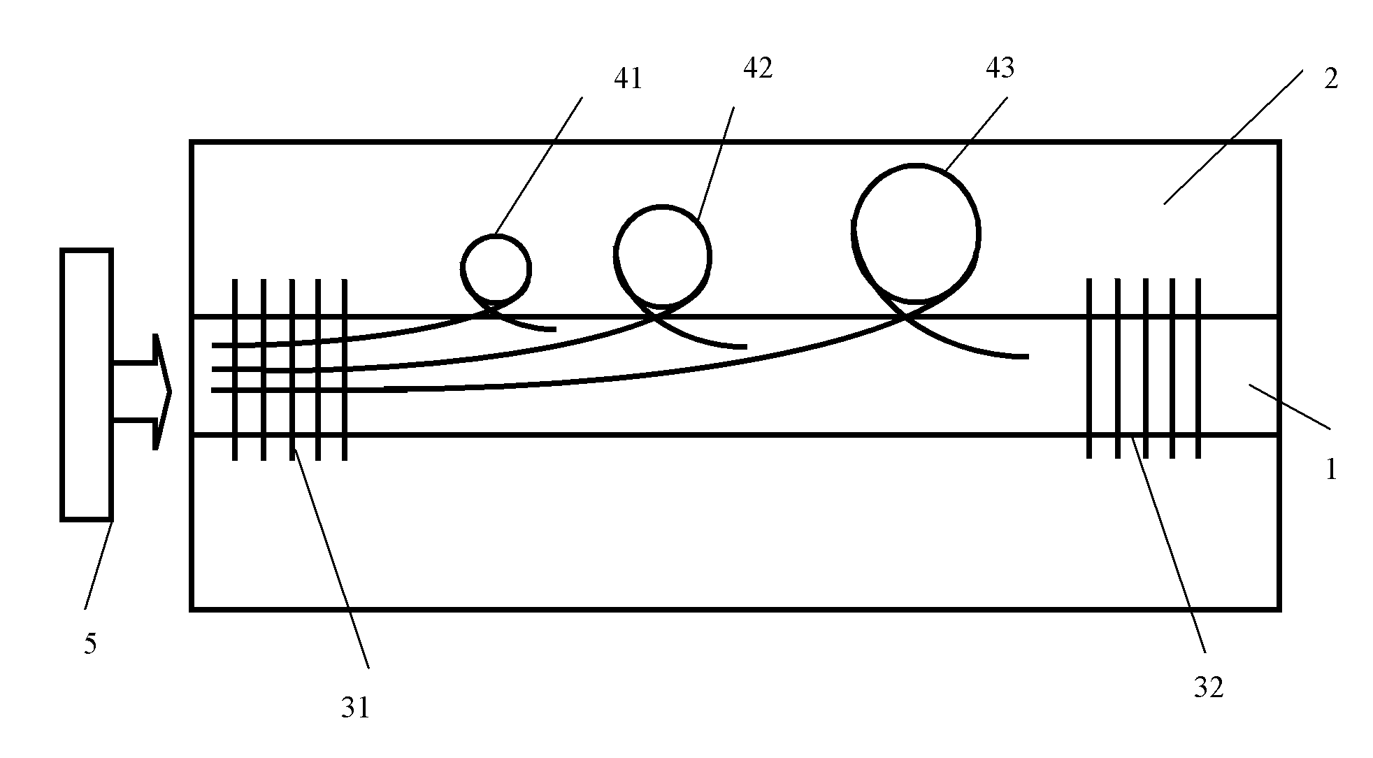
[0019] Embodiment 1, a multi-wavelength fiber laser with a micro-resonator structure, such as figure 1 shown. The laser structure includes: an optical fiber composed of a core 1 and a cladding 2, the first and second fiber gratings 31 and 32 are respectively written at both ends of the core 1, and the fiber gratings between the first and second fiber gratings 31 and 32 are The first, second and third micro-resonant cavities 41 , 42 and 43 , and the pumping laser 5 .
[0020] The first, second, and third microresonators 41, 42, and 43 are all composed of a ring and two tangent lines, and are all located at the junction of the core and the cladding, and are exposed to the optical fiber by an ultraviolet laser. The left tangent parts of each resonant cavity pass through the first fiber grating 31 .
[0021] The parameters of each part are: the radius of the core 1 is 2 microns; the thickness of the cladding 2 is 60.5 microns; the first fiber grating 31 is totally reflective to ...
Embodiment approach 2
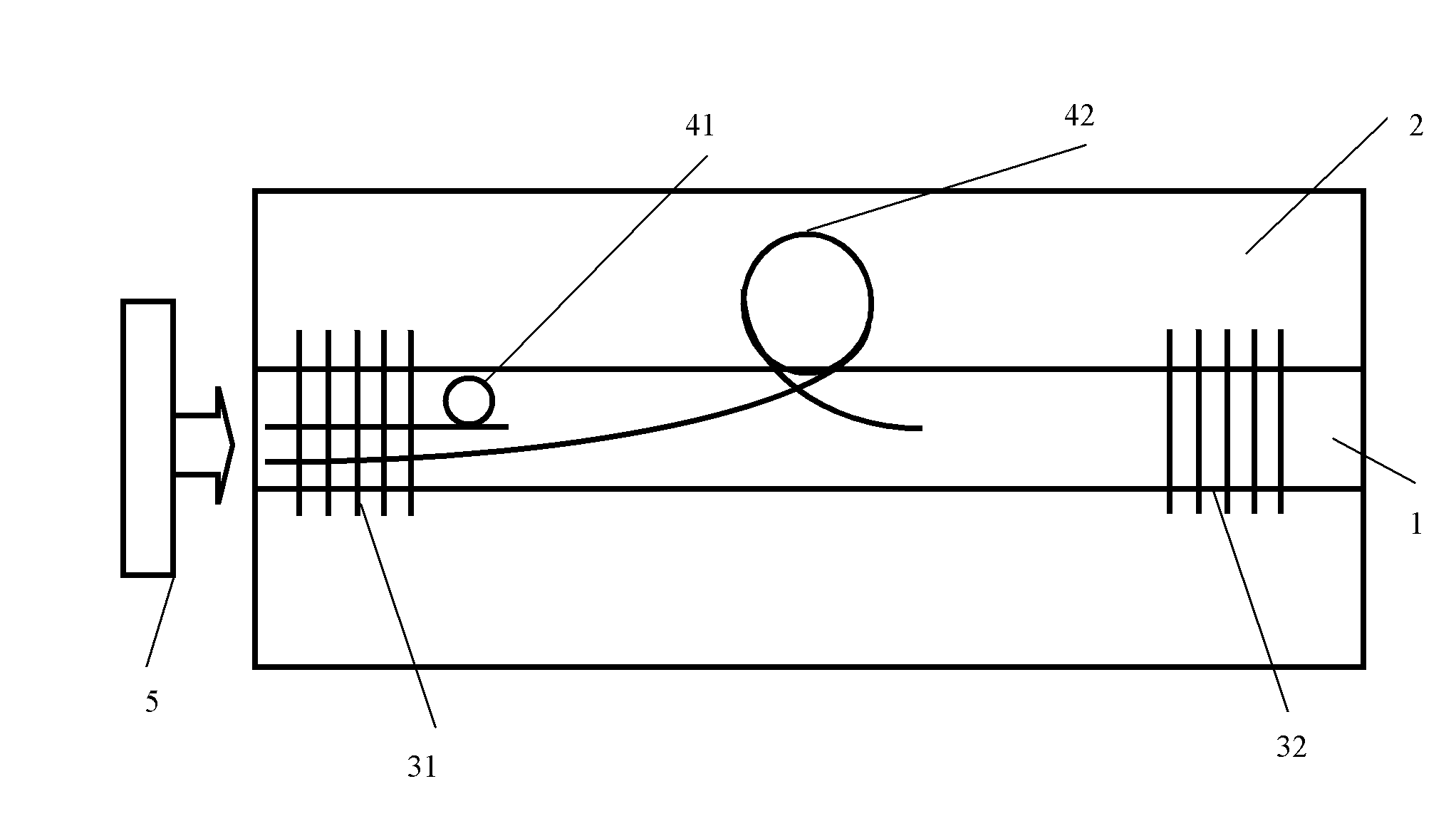
[0022] Embodiment 2, a multi-wavelength fiber laser with a micro-cavity structure, such as figure 2 shown. The laser structure includes an optical fiber composed of a core 1 and a cladding 2. First and second fiber gratings 31 and 32 are respectively written at both ends of the core 1, and the first and second fiber gratings 31 and 32 are located between the first and second fiber gratings. 1. Second, the micro-resonator bodies 41 and 42 and the pump laser 5 .
[0023] The first and second micro-resonant cavities 41, 42 are all made of a ring and two tangent lines. The first micro-resonant cavity 41 is located in the fiber core, and the second micro-resonant cavity 42 is located between the fiber core and the fiber core. The joints of the cladding are formed by exposing the optical fiber with a femtosecond laser, and the left tangent parts of each resonant cavity pass through the first fiber grating 31 .
[0024] The parameters of each part are: the radius of the core 1 is ...
Embodiment approach 3
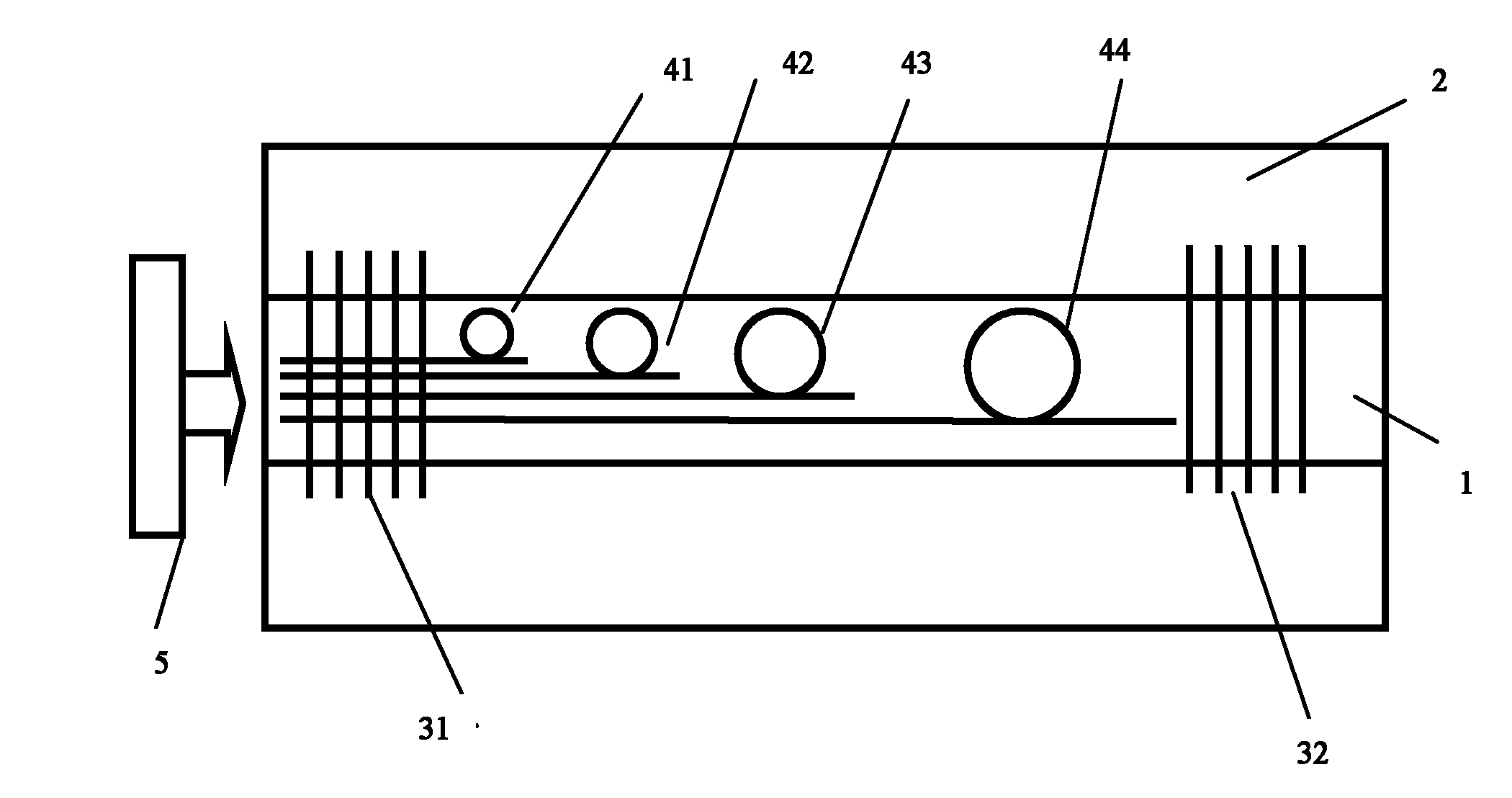
[0025] Embodiment 3, a multi-wavelength fiber laser with a micro-cavity structure, such as image 3 shown. The laser structure includes an optical fiber composed of a core 1 and a cladding 2. First and second fiber gratings 31 and 32 are respectively written at both ends of the core 1, and the first and second fiber gratings 31 and 32 are located between the first and second fiber gratings. 1. The second, third, and fourth micro-resonant cavities 41 , 42 , 43 , and 44 , and the pump laser 5 .
[0026] The first, second, third, and fourth micro-resonators 41, 42, 43, and 44 are all composed of a ring and two tangent lines, and are all located in the fiber core. They are formed by the femtosecond laser through the pair The optical fiber is exposed to form, and the tangent part on the left side of each resonant cavity passes through the first fiber grating 31 .
[0027] The parameters of each part are: the radius of the fiber core 1 is 9 microns; the thickness of the cladding 2...
PUM
 Abstract
Description
Claims
Application Information
 - R&D
- Intellectual Property
- Life Sciences
- Materials
- Tech Scout
- Unparalleled Data Quality
- Higher Quality Content
- 60% Fewer Hallucinations
Browse by: Latest US Patents, China's latest patents, Technical Efficacy Thesaurus, Application Domain, Technology Topic, Popular Technical Reports.
© 2025 PatSnap. All rights reserved.Legal|Privacy policy|Modern Slavery Act Transparency Statement|Sitemap|About US| Contact US: help@patsnap.com


