Fluorescent lamp

A fluorescent lamp and fluorescent powder technology, applied in the field of fluorescent lamps, can solve the problems of decreased color rendering, no discussion, no specific consideration of spectral distribution, etc., and achieve the effect of improving the color rendering index and improving the luminous efficiency.

Inactive Publication Date: 2011-05-25
PANASONIC CORP
View PDF3 Cites 5 Cited by
  • Summary
  • Abstract
  • Description
  • Claims
  • Application Information

AI Technical Summary

Problems solved by technology

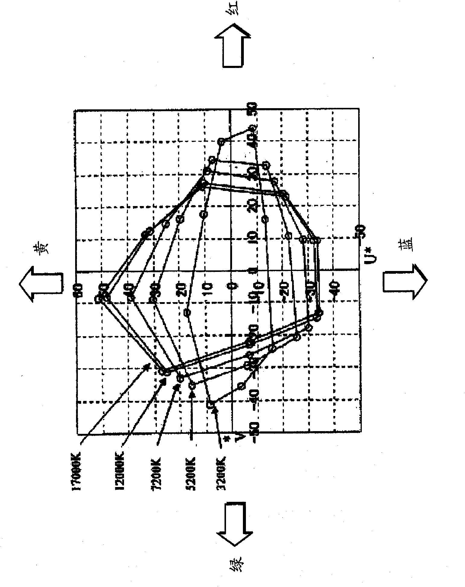
[0021] Therefore, there is no specific consideration of which kind of black body radiation locus deviation (Duv) or what kind of spectral distribution is desired.
[0022] In addition, in actual lighting applications, as a reaction to the high color temperature, the deterioration of the visual environment due to the decrease in color rendering has not been discussed, and there is no discussion on the color rendering index unique to ultra-high color temperature. The subject was proposed for research, but no evidence and improvement methods were found for the phenomenon, which cannot be represented by the simple average color rendering index Ra or the level of the special color rendering index Ri
[0023] Furthermore, after it is provided to the user as a lamp, in consideration of the reality that its use environment and illuminance are various, although it should be relatively simple to obtain the spectral absorption characteristics of the most basic light-receiving substance, that is, melanin, The action function (hereinafter referred to as the first action function) and the more complex action function (hereinafter referred to as The second action function) is optimized on both sides, but there is no method to optimize the two

Method used


Image

  • Fluorescent lamp
  • Fluorescent lamp
  • Fluorescent lamp

Examples


no. 1 Embodiment approach

[0298] Figure 10A A fluorescent lamp 100 according to an embodiment of the present invention is schematically shown. Figure 10B The cross-sectional structure of the fluorescent lamp 100 of this embodiment is schematically shown.

[0299] The fluorescent lamp 100 of the present embodiment is composed of a bulb (lamp arc tube) 10 made of a glass tube and a phosphor layer 20 on the inner surface of the bulb 10 . In the present embodiment, the light emitted from the fluorescent lamp 100 has a high color temperature with a correlated color temperature exceeding 7100 [K]. In other words, the fluorescent lamp 100 of the present embodiment is a fluorescent lamp having an ultra-high color temperature exceeding the upper color limit of 7100 [K] for common fluorescent lamps specified in JIS Z9112:1990 (or IEC 60081-1997).

[0300] The phosphor layer 20 of this embodiment includes red light emitting rare earth phosphor, green light emitting rare earth phosphor and blue light emitting ...

Embodiment approach 2

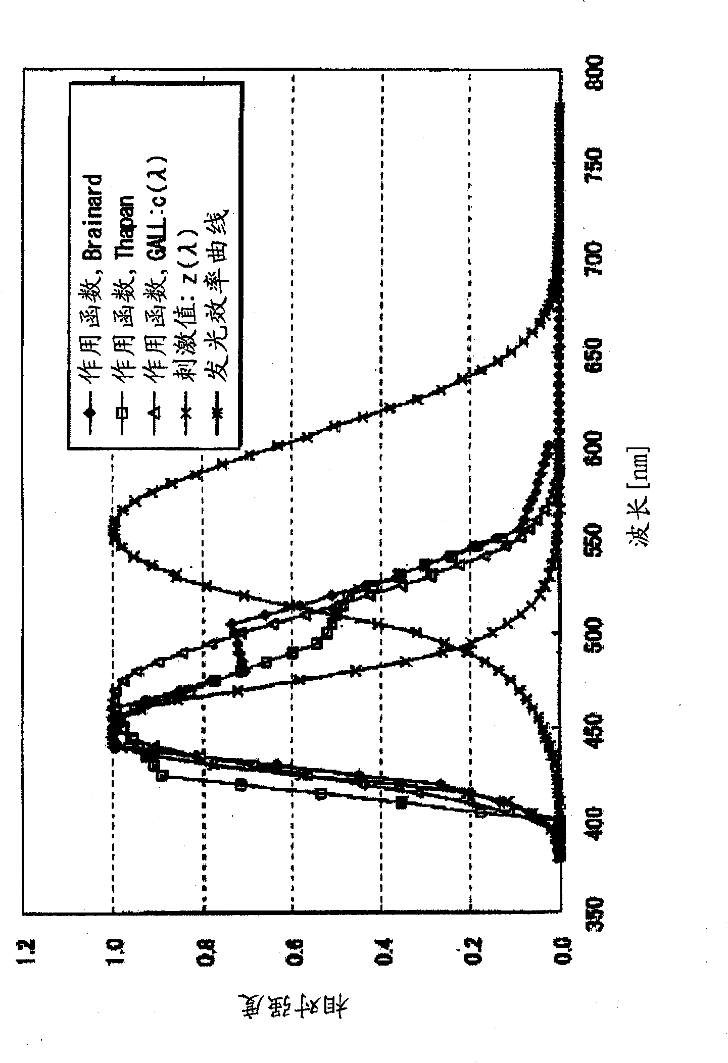
[0400] The second embodiment of the present invention is described below. In the second embodiment, when the luminescence main peak of the luminescence center of the theoretical spectral distribution is located between the main luminescence peaks of the blue luminescent phosphor and the green luminescent phosphor, and the ideal range is 480-520 [nm], according to the present invention The theoretical spectral distribution theoretically illustrates the relative tendency of the effects produced by the present invention.

[0401] First, as a theoretical model of an existing ordinary narrow-band emitting fluorescent lamp, a phosphor layer containing at least the following phosphors is theoretically simulated, namely: a red-emitting rare-earth phosphor containing a rare-earth element as a luminescent center, the luminescent The luminescence peak of the center is between 605 and 625 [nm]; the rare earth phosphor emitting green light contains rare earth elements as the luminescence c...

Embodiment approach 3

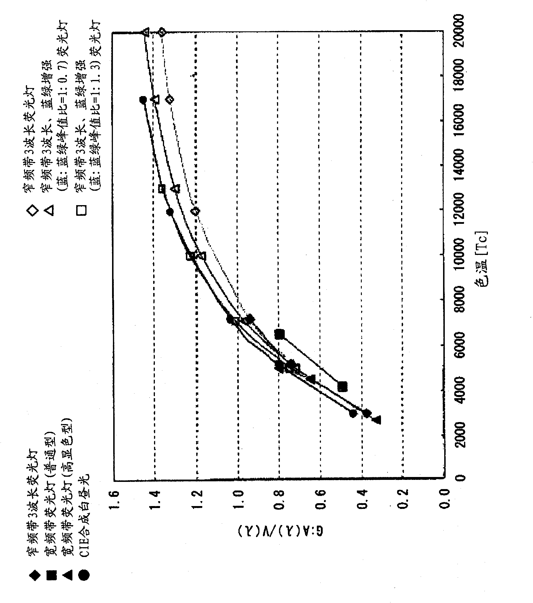
[0418] The third embodiment of the present invention theoretically illustrates the relativity of the effects produced by the present invention by extending the theoretical spectral distribution from the luminous peak of the blue-emitting rare earth phosphor to the half-maximum width on the longer wavelength side tendency.

[0419] Fig. 36 to Fig. 38 show: blue luminescence with a main luminescence peak between 440-460 [nm] in which the luminescence between the main luminescence peak of the green-emitting rare earth phosphor and the main luminescence peak of the blue-emitting rare earth phosphor is enhanced. Phosphor, in order to simulate the blue light-emitting phosphor with a half-peak width not less than 50 [nm] from the light-emitting peak to the longer wavelength side, the luminous intensity between 440 and 460 [nm] is assumed to be 100%, and the The luminous intensity of 50 [nm] from 460 [nm] to 510 [nm] on the longer wavelength side was assumed to be 50%, and the same si...


PUM


Abstract

Disclosed is a fluorescent lamp (100) having a light color with a correlated color temperature of more than 10,000 [K] and less than 17,000 [K] and DUV in the range of -2.5 to 5. The fluorescent lamp (100) comprises a lamp arc tube (10) and a phosphor layer (20). The phosphor layer (20) comprises at least a red light emitting rare earth phosphor, which serves as a luminescent center having a main emission peak (11) within 605 to 625 [nm], a green light emitting rare earth phosphor, which serves as a luminescent center having a main emission peak (12) within 540 to 550 [nm], and a blue light emitting rare earth phosphor, which serves as a luminescent center having a main emission peak (13) within 440 to 460 [nm]. The fluorescent lamp has an action function efficiency for melatonin suppression per unit light flux of more than 1.0 and an average color rendering index Ra of not less than 80. According to the above constitution, the fluorescent lamp allows to attain the function and effect of regulating the biological rhythm and promoting wakefulness of a living body while suppressing melatonin secretion and besides improves the drawbacks in color rendering characteristic of the light source.

Description

technical field [0001] The present invention relates to a fluorescent lamp that emits light that optically stimulates melatonin secretion and inhibition in living organisms. [0002] The fluorescent lamp of the present invention is a low-pressure discharge lamp coated with phosphor, such as a compact fluorescent lamp, a hot cathode fluorescent lamp, a cold cathode fluorescent lamp, an electrodeless fluorescent lamp, and a dielectric barrier discharge fluorescent lamp. In addition, the lighting device of the present invention refers to a lighting device using the fluorescent lamp of the present invention as the irradiation device. Background technique [0003] In recent years, melanin, which helps to form a photoperiodic biological rhythm, has been found in the human body. People are studying a lighting source technology, trying to inhibit the secretion of melatonin and realize the biological rhythm by optically stimulating melanin. adjustment or to promote the awakening of ...

Claims


Application Information

Patent Timeline
Patent Type & Authority Applications(China)
IPC IPC(8): A61N5/06
CPCH01J61/44A61N2005/0642A61N2005/0654A61N2005/0662A61N5/0618
Inventor 八木裕司清水正则东亨小林由季
Owner PANASONIC CORP
Why Eureka
Try Eureka