Silicon wafer pressure setting and applying clamp for plasma etcher

An etching machine and plasma technology, applied in the direction of discharge tube, sustainable manufacturing/processing, climate sustainability, etc., can solve the problems of inconsistent etching effect, inaccurate control of product quality, inability of pressurization device to pressurize accurately, etc.

Inactive Publication Date: 2011-06-01
EGING PHOTOVOLTAIC TECHNOLOGY CO LTD
View PDF5 Cites 8 Cited by
  • Summary
  • Abstract
  • Description
  • Claims
  • Application Information

AI Technical Summary

Problems solved by technology

[0003] In the solar cell plasma etching machine, the existing solar cell plasma etching fixture has a serious problem that the pressurization device cannot be accurately pressurized. Accurately controlling the pressure of the whole stack of silicon wafers can not ensure that the pressure around the silicon wafers is balanced, so that the etching effect is inconsistent and the product quality cannot be accurately controlled

Method used


Image

  • Silicon wafer pressure setting and applying clamp for plasma etcher
  • Silicon wafer pressure setting and applying clamp for plasma etcher

Examples


specific Embodiment approach

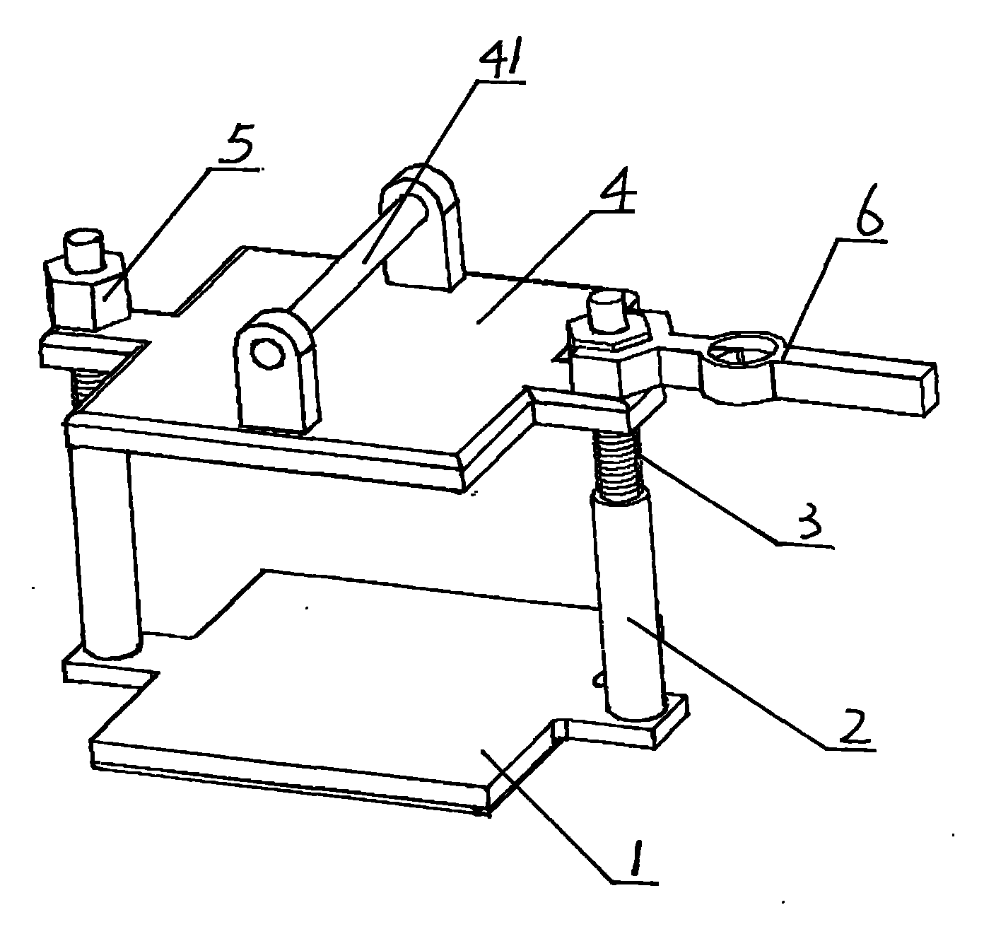
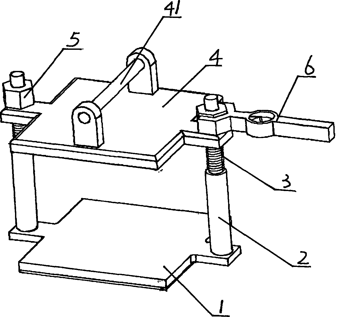
[0012] The silicon chip constant pressure pressure clamp of the plasma etching machine is composed of a clamp body 1, a column screw 2, a return spring 3, a pressure plate 4, a tightening nut 5 and a numerical control torque wrench 6, and the lower ends of the two column screws 2 are Fixed on the clamp body 1, threads are provided on the upper sections of the two column screws 2, the return spring 3 is set on the upper section of the column screws 2, and the pressure plate 4 is provided with a handle 41 and ear seats corresponding to the two column screws 2 , the pressure plate 4 is set on the two column screws 2 through the two ear seats, and is tightened by the tightening nut 5, and the tightening nut 5 is tightened by a numerical control torque wrench 6 with a fixed torque.


PUM


Abstract

The invention relates to a silicon wafer pressure setting and applying clamp for a plasma etcher, which comprises a clamp body, upright post screws, reset springs, pressing plates, tightening nuts and a numerical control torque wrench. The lower ends of the two upright post screws are fixed on the clamp body. The upper segments of the two upright post screws are provided with screw threads. The reset springs are sleeved on the upper segments of the upright post screws. The pressing plates are sleeved on the two upright post screws and are tightened by the tightening nuts. The tightening nuts are tightened by the numerical control torque wrench in a torque fixing mode. The whole stack of silicon wafers are arranged between the clamp body and the pressing plate and the pressing plate is tightened by the numerical control torque wrench through the two tightening nuts in a torque fixing mode, so that the pressure is set and applied to the whole stack of silicon wafers through the pressing plate. Therefore, the pressure of the whole stack of silicon wafers can be accurately controlled, nonuniform stress around the silicon wafers can be reduced, the products have consistent performance, and the etching effect is good.

Description

Technical field: [0001] The invention relates to a silicon chip pressurizing device of a solar battery plasma etching machine, which belongs to a fixture of the solar battery plasma etching machine. Background technique: [0002] A solar cell is actually a nonlinear PN junction with a relatively large area. During the manufacturing process, the silicon edge P-N junction formed in the diffusion process needs to be removed. Otherwise, the parallel resistance between the positive and negative electrodes of the battery will be too small and the leakage current will be reduced. If it is too large, it will affect the output characteristics of the battery. In large-scale production, CF4 is generally used to ionize in a high-frequency electric field, and the product reacts with Si to form SiF4 to remove the edge PN junction. Therefore, the silicon wafers need to be stacked and pressed tightly during the reaction process, otherwise, the diffusion layer on the silicon surface will al...

Claims


Application Information

Patent Timeline
Patent Type & Authority Applications(China)
IPC IPC(8): H01J37/32H01L31/18
CPCY02P70/50
Inventor 宋佳
Owner EGING PHOTOVOLTAIC TECHNOLOGY CO LTD
Why Eureka
Try Eureka