Self-exited push-pull converter

A self-excited push-pull, converter technology, applied in the direction of converting AC power input into DC power output, output power conversion devices, electrical components, etc., can solve the problem of high oscillation frequency, loss of DC-DC function, and slow rise of output voltage and other problems, to reduce the selection requirements, improve the conversion efficiency, and improve the effect of low output voltage

Active Publication Date: 2011-06-01
MORNSUN GUANGZHOU SCI & TECH
View PDF3 Cites 36 Cited by
  • Summary
  • Abstract
  • Description
  • Claims
  • Application Information

AI Technical Summary

Problems solved by technology

[0015] This unique sinusoidal oscillation at power-on, which is unstable and irregular, causes the output voltage of the DC-DC converter to be low when power-on, and the output voltage rises too slowly. It often takes several seconds to more than ten seconds to reach the rated output voltage. Cause the abnormal operation of the follow-up circuit, the single-chip microcomputer cannot be reset normally, the follow-up circuit does not work, cause the overall function disorder, and even cause major accidents
[0016] When power on, due to the extremely high frequency of this unstable oscillation, it is often close to the characteristic frequency f of the triode T , the collector current of the switching transistor TR1 or TR2 is very large, and it is easy to burn out. In actual use, this situation is often encountered, which makes the DC-DC function lose

Method used


Image

  • Self-exited push-pull converter
  • Self-exited push-pull converter
  • Self-exited push-pull converter

Examples


Embodiment Construction

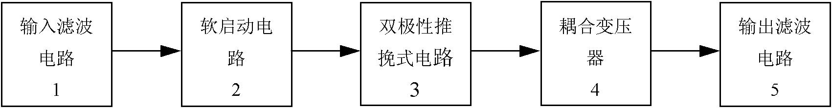
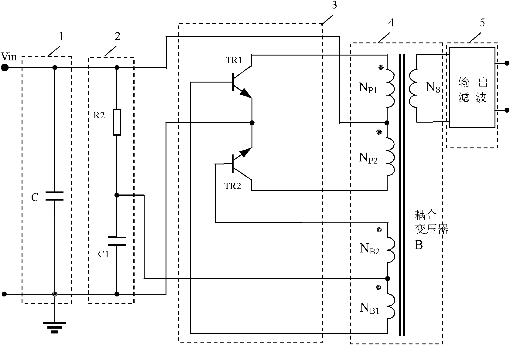
[0039] Figure 7 It is the first embodiment, as shown in the figure, including an input filter circuit, a soft start circuit, a bipolar push-pull circuit, a coupling transformer, and an output filter circuit connected in sequence, and the bipolar push-pull circuit includes a push-pull circuit The two triodes TR1 and TR2 in the pull connection relationship, the emitters of the two triodes share the ground, the bases of the two triodes are respectively connected to both ends of the feedback winding of the coupling transformer, and the collectors of the two triodes are respectively connected to both ends of the primary winding of the coupling transformer

[0040] with existing technology figure 2 The difference is that: a high-frequency self-excitation suppression circuit is added to eliminate the sinusoidal oscillation caused by the high characteristic frequency of the push-pull transistor when it is powered on; the high-frequency self-excitation suppression circuit is connecte...


PUM


Abstract

The invention discloses a self-exited push-pull converter, comprising an input soft starting circuit, a bipolar push-pull circuit, a coupling transformer and an output filter circuit, wherein the input soft starting circuit, the bipolar push-pull circuit, the coupling transformer and the output filter circuit are connected in order; the bipolar push-pull circuit comprises two triodes and a high frequency self-exited suppression circuit, wherein the two triodes are in push-pull connection; the emitters of the two triodes are grounded; the bases of the two triodes are respectively connected with two ends of a feedback winding of the coupling transformer; the collectors of the two triodes are connected with two ends of a primary winding of the coupling transformer; the high frequency self-exited suppression circuit is used for removing sine vibration generated due to high characteristic frequency when the triodes are electrified; and the high frequency self-exited suppression circuit is connected in the bipolar push-pull circuit. The self-exited push-pull converter can effectively control high frequency vibration.

Description

technical field [0001] The invention relates to a self-excited push-pull converter for realizing DC-DC or DC-AC conversion in industrial control and lighting industries. Background technique [0002] Existing self-excited push-pull converter application one, such as ZL patent No. 03273278.3, date of publication: August 25, 2004, titled "Self-excited push-pull converter" described in the article, including input filter circuit 1 , soft start circuit 2, bipolar push-pull circuit 3, coupling transformer 4, output filter circuit 5, the schematic block diagram is shown in figure 1 , the schematic diagram is as figure 2 shown. [0003] Its circuit structure is: the input filter capacitor C is connected between the voltage input terminal and the ground to filter the input voltage; the filtered input voltage is connected to the soft start circuit, and the soft start circuit is composed of a resistor R2 and a capacitor C1, and the resistor R2 and Capacitor C1 is connected in seri...

Claims


Application Information

Patent Timeline
Patent Type & Authority Applications(China)
IPC IPC(8): H02M7/517H02M7/519
Inventor 王保均
Owner MORNSUN GUANGZHOU SCI & TECH
Why Eureka
Try Eureka