
Method of coaxial lighting in Coulter micro-hole of full-functional blood analyzer and analyzer therefor

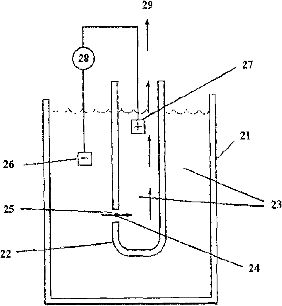
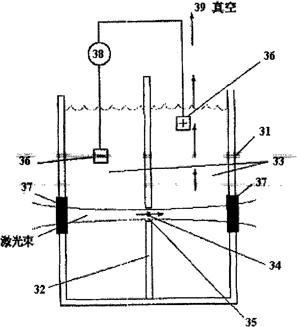
A technology for Coulter microwell and blood analysis, which is applied to the coaxial illumination method of Coulter microwell and its analytical instrument field, can solve the problems of the structure and cost being far apart, and achieves the improvement of the signal-to-noise ratio and the improvement of the The effect of discrimination

Inactive Publication Date: 2011-06-08
龚维燕
View PDF8 Cites 15 Cited by
  • Summary
  • Abstract
  • Description
  • Claims
  • Application Information

AI Technical Summary

Problems solved by technology

[0020] 6. Backward light scattering
The methods given in these patents all use multiple optical fibers and multiple photomultiplier tubes to detect backscattered light signals, and their structure and cost are far from the requirements of practical commercial instruments.

Method used


Image

  • Method of coaxial lighting in Coulter micro-hole of full-functional blood analyzer and analyzer therefor
  • Method of coaxial lighting in Coulter micro-hole of full-functional blood analyzer and analyzer therefor
  • Method of coaxial lighting in Coulter micro-hole of full-functional blood analyzer and analyzer therefor

Examples


Embodiment 1

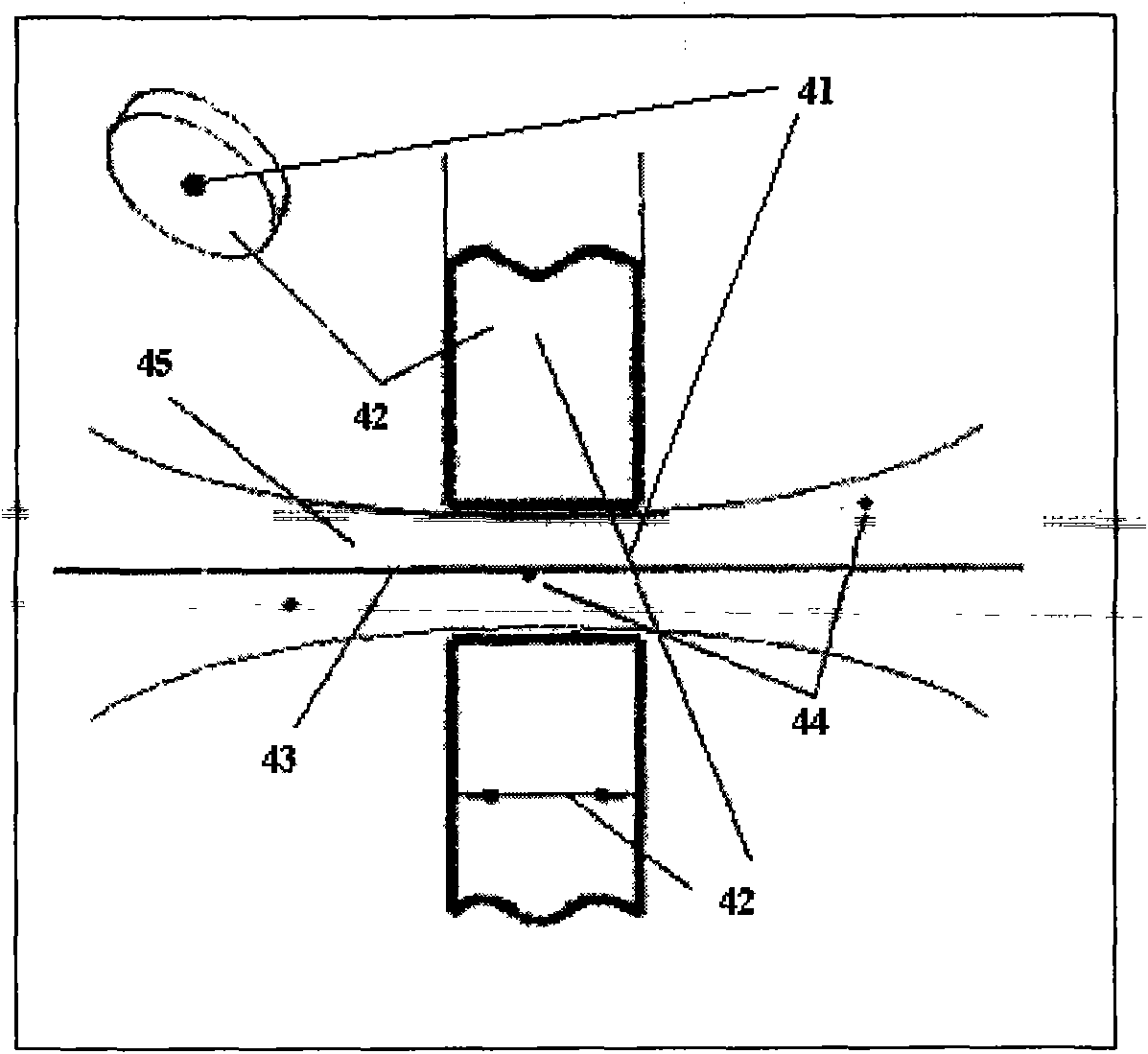
[0182] see Figure 10 , the laser 13, such as a fiber-coupled laser, the output light of the optical fiber 12 enters the illumination optical system 8 through the beam splitter 11, and the focused light beam 7 is focused to the blood cell 4 in the center of the microwell through the optical window 6 (right side) of the microwell pool superior. The forward scattered light (FLS) or axial light loss (ALL) generated by the interaction between the irradiated light and the blood cells enters the forward scattered light receiving optical system 14 through the optical window 6 (on the left) of the microwell cell. The backscattered light (BLS) generated by the interaction between the irradiated light and the blood cells 4 returns to the backscattered light receiving optical system (including the illumination optical system 8 , the beam splitter 11 and the backscattered light receiving optical system 10 ) through the microporous pool window 6 ), the real-time monitoring optical system ...

Embodiment 2

[0184] see Figure 11 The difference between this implementation method and the specific implementation method 1) is that the illumination optical system and the backscattered light receiving optical system have no common parts, and the design of the microwell pool is also different from the above-mentioned implementation method 1). The output of the fiber-coupled laser 13 first enters the illumination optical system 8 through the optical fiber 12, then passes through the beam splitter 11 and becomes a focused beam 7, which is focused on the blood cell 4 in the center of the microwell through the optical window 6 (right) of the microwell pool. The forward scattered light (FLS) or axial light loss (ALL) generated by the interaction between the irradiated light and the blood cells enters the forward scattered light receiving optical system 14 through the optical window 6 (on the left) of the microwell cell. The backscattered light (BLS) generated by the interaction between the i...


PUM


Abstract

Disclosed are a method of coaxial lighting in Coulter micro-hole and the analyzer therefore. Lighting beams coaxial with the axis of a Coulter micro-hole directly coaxilly shine on Coulter micro-hole. Such a special design makes it possible for applying backward light-scattering detection sensitive to inner composition and structure of particles to commercial blood analyzer, thereby greatly improving the identification capability of an analyzer. Neither expensive flow-type cell boxes and complex fluid focusing system nor other additional methods which might increase the complexity for operating the analyzer, such as reagent treatment and fluorescence dyeing, are required in the invention. Based on Coulter principle and light scattering, five-differential blood cell analyzing and counting can be realized, and comprehensive detection and analysis providing more parameters also can be completed. Compared with high-end blood analyzers based on flow cytometry dominating the market, the analyzer provided in the invention is high in performance-price ratio and sharp in market competitive edges.

Description

technical field [0001] The invention relates to a blood cell analysis method and instrument of a medical testing instrument, in particular to a coaxial lighting method for Coulter microholes in a full-function blood analysis instrument and an analysis instrument thereof. Background technique: [0002] 1. Historical review [0003] Blood cell analyzer, also known as blood cell counter, is one of the most commonly used important clinical testing instruments for counting and classifying various constituent cells in blood. An attempt was made to count red blood cells in 1852, and a method for counting blood cells appeared in 1855. This method of manual microscopic inspection with a microscope is time-consuming and laborious. It requires professionally trained operators, and it is difficult to report in time when a large number of specimens are inspected, and there are human counting errors. [0004] In 1949, American Wallace H. Coulter (Wallace H. Coulter) successfully submitt...

Claims


Application Information

Patent Timeline
Patent Type & Authority Applications(China)
IPC IPC(8): G01N15/12
CPCG01N15/1218G01N15/1459G01N15/13
Inventor 龚维燕
Owner 龚维燕
Learn More