High precision full optical fiber current mutual inductor

A current transformer and all-optical fiber technology, applied in the direction of voltage/current isolation, etc., can solve the problems of poor anti-interference ability of optical fiber phase modulator, environmental temperature, vibration, and large influence of polarized light, etc., to improve the signal-to-noise ratio and anti-interference ability, improve reliability and reduce deflection error

Inactive Publication Date: 2011-06-08
广州同汇盛南站产业发展有限公司
View PDF6 Cites 30 Cited by
  • Summary
  • Abstract
  • Description
  • Claims
  • Application Information

AI Technical Summary

Problems solved by technology

The disadvantages of active electronic transformers are: the power supply cost of the remote acquisition module is high, the working environment of electronic components is harsh and easy to age, and the remote module is located at the high-voltage end, which is inconvenient for maintenance
The current transformer with magneto-optical glass structure uses heavy flint magneto-optic glass with high Field constant as the carrier, so that the linearly polarized light is modulated by the measured current to change the deflection angle when it bypasses it, and then passes through the Wollaston prism for detection. The deflection device is used to detect the deflection angle to indirectly measure the current. This scheme is an open-loop mode. The optical system is made of independent optical devices. The optical devi...

Method used


Image

  • High precision full optical fiber current mutual inductor
  • High precision full optical fiber current mutual inductor
  • High precision full optical fiber current mutual inductor

Examples


Embodiment Construction

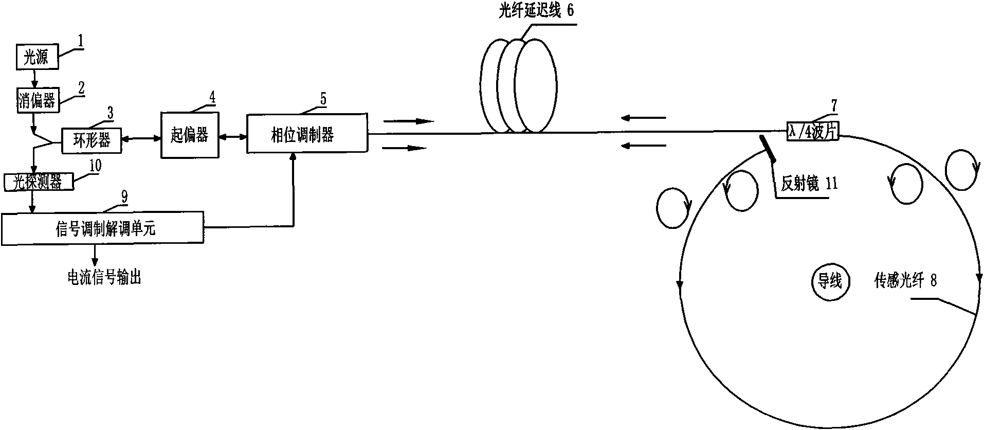
[0019] refer to figure 1 , a high-precision all-fiber current transformer, including an optical system and a signal modulation and demodulation unit 9, the optical system includes a light source 1, and the light source 1 is sequentially connected to a depolarizer 2, a circulator 3, a polarizer 4, a phase Modulator 5, fiber delay line 6, λ / 4 wave plate 7, sensing fiber 8, fiber optic mirror 11, the light beam emitted by the light source 1 is depolarized by the depolarizer 2 and then enters the polarizer 4 through the circulator 3 and becomes Linearly polarized light; the pigtail of the polarizer 4 and the pigtail of the phase modulator 5 are fused at an angle of 45°, so that the linearly polarized light is divided into two orthogonal beams transmitted along the fast axis and the slow axis of the polarization-maintaining fiber respectively mode of linearly polarized light; two beams of linearly polarized light are modulated into a trigonometric function waveform with a light i...


PUM


Abstract

The present invention discloses a high precision full optical fiber current mutual inductor, comprising an optical path system and a signal modulation and demodulation unit. The optical path system includes an optical source connected in order with a depolarizer, a circulator, a polarizer, a phase modulator, an optical fiber delay line, a lambda/4 wave plate, a sensing optical fiber and an optical fiber reflector, and also includes a photodetector connected with the signal modulation and demodulation unit. The high precision full optical fiber current mutual inductor realizes the phase closed loop control of the optical fiber current mutual inductor through a signal modulation and demodulation unit and a phase modulator, thereby greatly increasing the ratio of signal to noise and the anti-interference capability of the system. The high precision full optical fiber current mutual inductor employs the full optical fiber structure and the closed loop detection control loop thereby increasing the reliability of the system, and employs an ultra-low double refractive index and high Field constant rotating optical fiber as the sensing optical fiber thereby reducing the offset error of the polarized light in the process of the optical path transmission, and can be widely used in the field of electric power detection.

Description

technical field [0001] The invention relates to a current transformer, in particular to an all-optical fiber current transformer. Background technique [0002] The transformer is the eyes of the power system. It detects the voltage or current of the line through the transformer and realizes isolation from the primary equipment. At the same time, it cooperates with the secondary equipment to realize the functions of measurement, protection, measurement and control of the power system. The structure of the traditional electromagnetic current transformer is similar to that of a transformer. The line wire is used as the primary winding, and the electromagnetic is transmitted to the secondary coil in the short-circuit state through the silicon steel sheet iron core. The current induced by the secondary coil and the current generated by the primary coil are in the silicon steel sheet. cancel each other out in the core, I 1 *N 1 = I 2 *N 2 , so that a secondary current proporti...

Claims


Application Information

Patent Timeline
IPC IPC(8): G01R15/24
Inventor 吴明玉邓忠华
Owner 广州同汇盛南站产业发展有限公司
Why Eureka
Try Eureka