Method for improving photoetching critical dimension in groove process

A trench and lithography technology, applied in the photoengraving process, optics, optomechanical equipment and other directions of the pattern surface, which can solve the problems of BARC thickness and so on.

Inactive Publication Date: 2011-06-08
SHANGHAI HUA HONG NEC ELECTRONICS
View PDF0 Cites 16 Cited by
  • Summary
  • Abstract
  • Description
  • Claims
  • Application Information

AI Technical Summary

Problems solved by technology

However, a simple spin-coating of BARC may not be able to completely p

Method used


Image

  • Method for improving photoetching critical dimension in groove process
  • Method for improving photoetching critical dimension in groove process
  • Method for improving photoetching critical dimension in groove process

Examples


Embodiment Construction

[0014] In an embodiment of the present invention, the method for improving the critical dimension of photolithography in the trench process is to planarize the silicon wafer with steps after the trench is formed and before the photoresist is coated. These include a photolithography and a BARC spin coating. Specifically include the following steps:

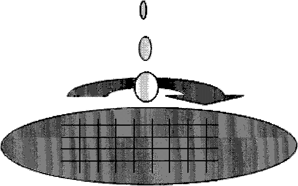
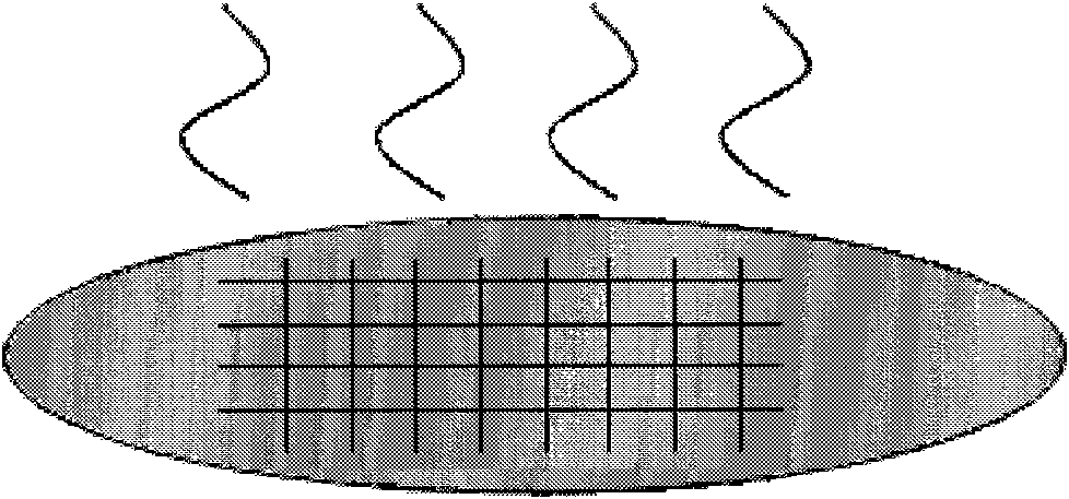
[0015] Step one, combine Figure 7 As shown, the negative photoresist was spin-coated and baked. Spin-coat negative-tone photoresist on the surface of the trench and silicon wafer, and then bake. The negative photoresist refers to a photoresist whose polarity is opposite to that of traditional trench lithography. If negative resist is used in trench lithography, positive resist is spin-coated, and so on. The negative photoresist can be G-line, I-line, KrF, ArF or even a photoresist suitable for shorter wavelengths, and its thickness is not limited.

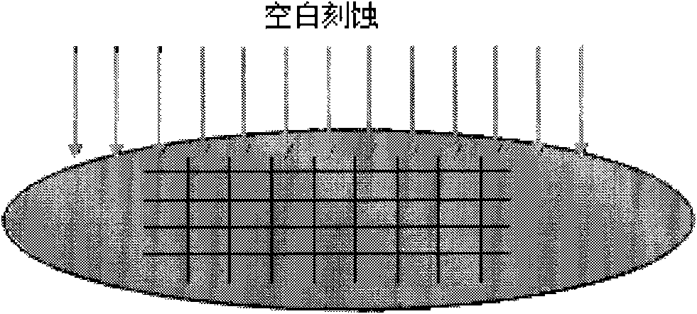
[0016] Step two, combine Figure 8 As shown, use the mask plate with the groo...


PUM


Abstract

The invention discloses a method for improving a photoetching critical dimension in a groove process. The method comprises the following steps of: 1, spin-coating negative photoresist on the surfaces of a groove and a silicon wafer and then roasting; 2, carrying out exposure and development by using a maskplate with a graph of a groove of a front layer; and 3, spin-coating a bottom antireflection coating (BARC) on a graph formed in the groove and roasting. By the method, the control capacity of the photoetching critical dimension (CD) in the groove process can be improved and a process window can be optimized.

Description

technical field [0001] The invention relates to the field of semiconductor integrated circuits, in particular to a method for improving critical dimensions of photolithography in trench technology. Background technique [0002] At present, when the groove is etched, the step difference caused by the depth of the groove and the data ratio of the groove itself will bring great challenges to the subsequent photolithography process, especially for critical dimensions. control. For the step difference caused by the trench depth, the subsequent photolithography process mainly uses BARC (bottom anti-reflective coating) or chemical material spin coating, or blank etching to plan the surface. Specific methods such as Figure 1-6 shown, in sequence including: the first spin-coating of the chemical fill material (see figure 1 ), the first chemical fill material bake (see figure 2 ), blank etch (see image 3 , or without this step), the second chemical filling material spin coatin...

Claims


Application Information

Patent Timeline
IPC IPC(8): G03F7/00
Inventor 阚欢吴鹏
Owner SHANGHAI HUA HONG NEC ELECTRONICS
Why Eureka
Try Eureka