
Synchronized motion error correction and control system of photoetching machine worktable

A technology of synchronous movement and control system, applied in microlithography exposure equipment, photolithography process exposure devices, etc., can solve the problems of silicon wafer table and mask error correction, complex structure, error control accuracy, etc., to achieve reliable operation, High control accuracy and the effect of synchronous motion error correction

Inactive Publication Date: 2011-06-08
INST OF OPTICS & ELECTRONICS - CHINESE ACAD OF SCI
View PDF5 Cites 14 Cited by
  • Summary
  • Abstract
  • Description
  • Claims
  • Application Information

AI Technical Summary

Problems solved by technology

[0008] In order to solve the defects of complex structure and low error control precision existing in the workpiece table synchronous motion control system, the purpose of the present invention is to provide a control system mainly used in step-scan lithography machine silicon wafer table and mask synchronous motion error correction system

Method used


Image

  • Synchronized motion error correction and control system of photoetching machine worktable
  • Synchronized motion error correction and control system of photoetching machine worktable
  • Synchronized motion error correction and control system of photoetching machine worktable

Examples


Embodiment Construction

[0031] The implementation of the present invention will be described below with a specific control flow, and those skilled in the art can understand the functions and advantages of the present invention according to the content disclosed in this specification.

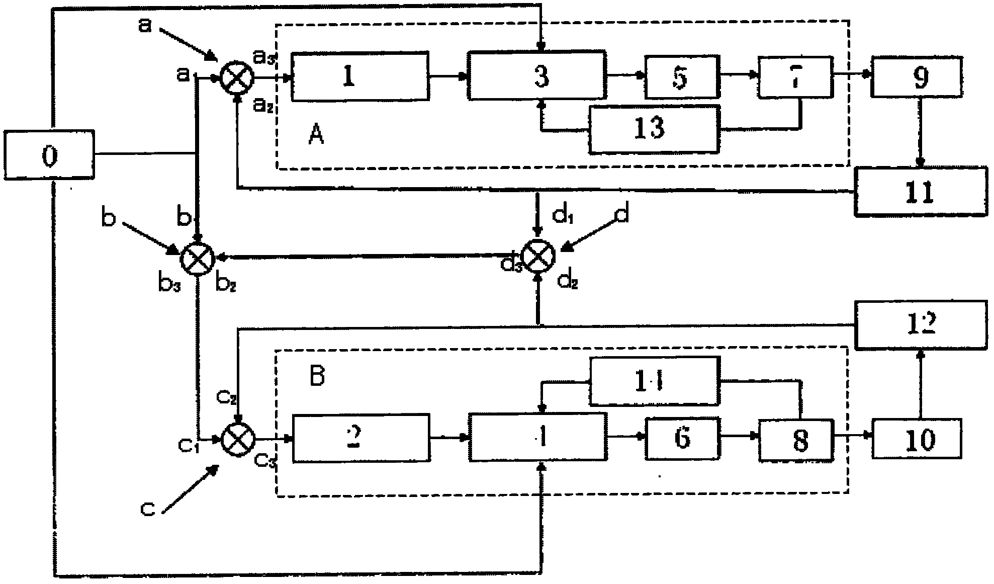
[0032] Such as figure 1 The shown lithography machine workpiece table synchronous motion error correction control system, the system includes an industrial computer 0, a silicon wafer table 9, a mask table 10, a first position sensor 11, a second position sensor 12, and a first detection unit A , the second detection unit B, the first computing unit a, the second computing unit b, the third computing unit c and the fourth computing unit d, wherein:

[0033] The industrial computer 0 has a first output terminal, a second output terminal and a third output terminal;

[0034] The first detection unit A has a first input terminal, a second input terminal and an output terminal;

[0035] The second detection unit B has a ...


PUM


Abstract

The invention relates to a synchronized motion error correction and control system of a photoetching machine worktable. The system comprises an industrial computer, a wafer stage, a mask stage, a first position sensor, a second position sensor, a first detection unit, a second detection unit, a first calculation unit, a second calculation unit, a third calculation unit and a fourth calculation unit and is mainly used for correcting a synchronized motion error between the wafer stage and the mask stage in a stepping scanning photoetching machine. The system adopts a synchronization error composite correction control method combining reverse feedback and feedforward control and forms double closed loop speed control and position control by a speed ring and a position ring, an outer ring position sensor is used as a feedback device to output a position feedback signal to a position controller, and an inner ring speed sensor is used as a feedback device to output a speed feedback signal to a speed controller. The position controller calculates and corrects the synchronization error between the wafer stage and the mask stage according to the position feedback signal.

Description

technical field [0001] The invention relates to the technical field of special equipment for microelectronics, in particular, it is used in a step-and-scan photolithography machine to realize the error correction control of the synchronous movement of a silicon wafer stage and a mask stage. Background technique [0002] The workpiece table technology is one of the key technologies to realize the overall performance of the lithography machine. Different from the traditional step-and-repeat lithography machine, the imaging quality of the step-and-scan lithography machine depends not only on the optical system, but also on the dynamic positioning and dynamic synchronous motion performance of the wafer stage and mask stage. [0003] At present, the synchronous control of wafer stage and mask stage can be roughly divided into the following three categories: [0004] The first type is a synchronous control strategy based on the coordination of wafer stage and mask stage. The waf...

Claims


Application Information

Patent Timeline
IPC IPC(8): G03F7/20
Inventor 马平胡松陈磊胡淘
Owner INST OF OPTICS & ELECTRONICS - CHINESE ACAD OF SCI
Learn More