Method for manufacturing shallow groove isolation structure

A technology of isolation structure and manufacturing method, which is applied in semiconductor/solid-state device manufacturing, electrical components, circuits, etc., and can solve problems such as easy breakdown

Inactive Publication Date: 2011-06-08
CSMC TECH FAB1 +1
View PDF8 Cites 9 Cited by
  • Summary
  • Abstract
  • Description
  • Claims
  • Application Information

AI Technical Summary

Problems solved by technology

[0009] The present invention solves the problem that there is a sharp chamfer at the top of the shallow trench formed in the prior ar

Method used


Image

  • Method for manufacturing shallow groove isolation structure
  • Method for manufacturing shallow groove isolation structure
  • Method for manufacturing shallow groove isolation structure

Examples


Embodiment approach

[0023] refer to Figure 5 As shown, one embodiment of the manufacturing method of the shallow trench isolation structure of the present invention includes:

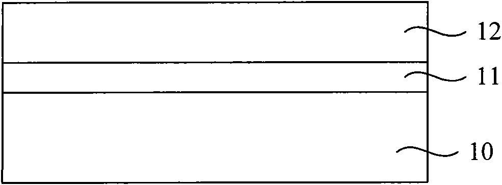
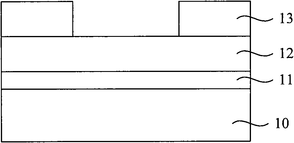
[0024] Step s1, after forming an opening to expose the hard mask of the substrate, placing the substrate in an oxygen atmosphere for oxidation treatment;

[0025] Step s2, after the oxidation treatment, dry etching is used to form a shallow trench in the substrate at the opening.

[0026] In combination with the aforementioned analysis, in the implementation of the method for manufacturing the shallow trench isolation structure above, a thin oxide layer is formed at the joint between the hard mask and the substrate through oxidation treatment. The thin oxide layer is etched very little during the dry etching process for forming the shallow trench after the oxidation treatment, so that the shape of the top of the finally formed shallow trench follows the shape covered by the thin oxide layer. Therefore, the thin oxide la...


PUM


Abstract

The invention discloses a method for manufacturing a shallow groove isolation structure, which comprises: forming a hard mask of which an opening exposes from a substrate, and oxidizing the substrate in an oxygen atmosphere; and forming a shallow groove on the substrate at the position of the opening by a dry etching method after the oxidation treatment. The method for manufacturing the shallow groove isolation structure can form a relatively round shallow groove top chamber and reduce the probability of process defects.

Description

technical field [0001] The invention relates to the technical field of semiconductor manufacturing, in particular to a manufacturing method of a shallow trench isolation structure. Background technique [0002] Currently, device isolation using shallow trench isolation technology has become a conventional technology. Figure 1 ~ Figure 4 It is a schematic diagram of a part of the manufacturing process of a common shallow trench isolation structure. refer to figure 1 As shown, first, a field oxide layer 11 and a nitride layer 12 are sequentially formed on a silicon substrate 10 . refer to figure 2 As shown, then, a photoresist layer is formed on the nitride layer 12, and a photoresist pattern 13 is formed by photolithography, and the photoresist pattern 13 is used to define the shape of the shallow trench. refer to image 3 As shown, thereafter, using the photoresist pattern 13 as a mask, the nitride layer 12 and the field oxide layer 11 are sequentially etched to form ...

Claims


Application Information

Patent Timeline
IPC IPC(8): H01L21/762
Inventor 许宗能蒋昆坤任华任小兵
Owner CSMC TECH FAB1
Why Eureka
Try Eureka