Laser pulse spot welding method for metal sheet
A technology of laser pulses and material thin plates, applied in laser welding equipment, metal processing, metal processing equipment, etc., can solve the problems of large material burning loss, easy generation of pores, cracks, etc., achieve smooth surface, reduce pores, and improve welding speed effect
Inactive Publication Date: 2011-06-15
HARBIN INST OF TECH
View PDF4 Cites 34 Cited by
- Summary
- Abstract
- Description
- Claims
- Application Information
AI Technical Summary
Problems solved by technology
The purpose of the present invention is to solve the problems that the current laser spot welding process has a large burning loss of materials and easily produces pores, cracks and slump defects
Method used
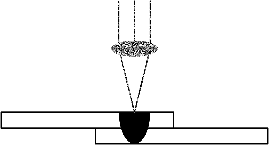
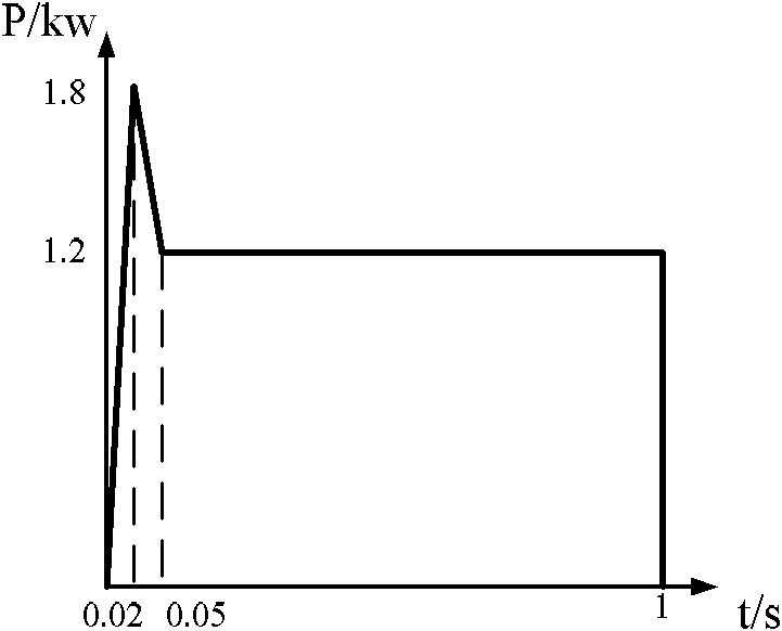
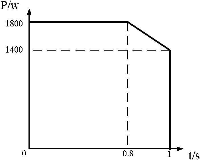
View moreImage
Smart ImageViewing Examples
Examples
specific Embodiment approach 1
specific Embodiment approach 2
specific Embodiment approach 3
Login to View More PUM
 Abstract
The invention relates to a novel laser spot welding method, in particular relates to a laser pulse spot welding method for a metal sheet, aiming at solving the problems that in the prior art, the burning loss of the material is high, air holes, cracks and collapse are easy to generate in the laser spot welding process, and particularly the reflectivity of the aluminum alloy material to laser is high so that the stability in the spot welding process is poor. The laser pulse spot welding method for a metal sheet comprises the following specific steps: (1) preprocessing a workpiece to be welded, (2) fixing the workpiece to be welded, and (3) welding by adopting the laser pulse spot welding method. The laser pulse spot welding method for a metal sheet has the advantages of enhancing the welding efficiency, improving the welding spot quality, ensuring good uniformity of the sizes of the welding spots and realizing the spot welding of a plate of moderate thickness by a small-power laser. The laser pulse spot welding method for a metal sheet is mainly used for welding metal materials and particularly used for welding the metal sheet.
Description
A laser pulse spot welding method for metal material sheet technical field The invention relates to a novel laser spot welding method, in particular to a laser pulse spot welding method for metal material thin plates. Background technique Spot welding technology is currently the most important connection method for connecting thin plate lap joints. As a mature welding process, it is widely used in various industrial productions. There are many types of spot welding, including traditional resistance spot welding and arc spot welding, as well as laser spot welding, friction stir spot welding and composite spot welding, which have developed rapidly in recent years, as shown in Table 1. Laser spot welding is a new high-efficiency and high-precision spot welding method using laser as a heat source. The welding spot has a large depth-to-width ratio and small deformation. Especially, the single-sided non-contact welding method can greatly enhance the impact of the spot welding pr...
Claims
Login to View More Application Information
Patent Timeline
 Patent Type & Authority Applications(China)
IPC IPC(8): B23K26/22B23K26/42B23K101/18B23K26/60
Inventor 陶汪李俐群王铭茂
Owner HARBIN INST OF TECH
Features
- R&D
- Intellectual Property
- Life Sciences
- Materials
- Tech Scout
- Unparalleled Data Quality
- Higher Quality Content
- 60% Fewer Hallucinations
Learn More Browse by: Latest US Patents, China's latest patents, Technical Efficacy Thesaurus, Application Domain, Technology Topic, Popular Technical Reports.
© 2025 PatSnap. All rights reserved.Legal|Privacy policy|Modern Slavery Act Transparency Statement|Sitemap|About US| Contact US: help@patsnap.com


