Heat exchange tube internally provided with spiral fins and application thereof
A heat exchange tube and spiral fin technology is applied in the field of energy and chemical industry, which can solve the problems of difficulty in processing and casting, low heat transfer efficiency, and tube wall scouring, and achieve the effects of reducing production capacity consumption, improving heat transfer efficiency, and reducing scouring wear.
Inactive Publication Date: 2011-06-15
EAST CHINA UNIV OF SCI & TECH
View PDF6 Cites 29 Cited by
- Summary
- Abstract
- Description
- Claims
- Application Information
AI Technical Summary
Problems solved by technology
In order to solve the existing problems in the past, the purpose of the present invention is to provide a heat exchange tube with built-in spiral fins to overcome the low heat transfer efficiency of the traditional ethylene cracking furnace tube, easy coking, serious erosion of the tube wall by high-speed fluid, difficulty in processing and casting, etc. Defects, one or more spiral fins are manufactured inside the heat exchange tube to enhance heat transfer
Method used
View moreImage
Smart ImageViewing Examples

Examples
Embodiment
Login to View More PUM
 Abstract
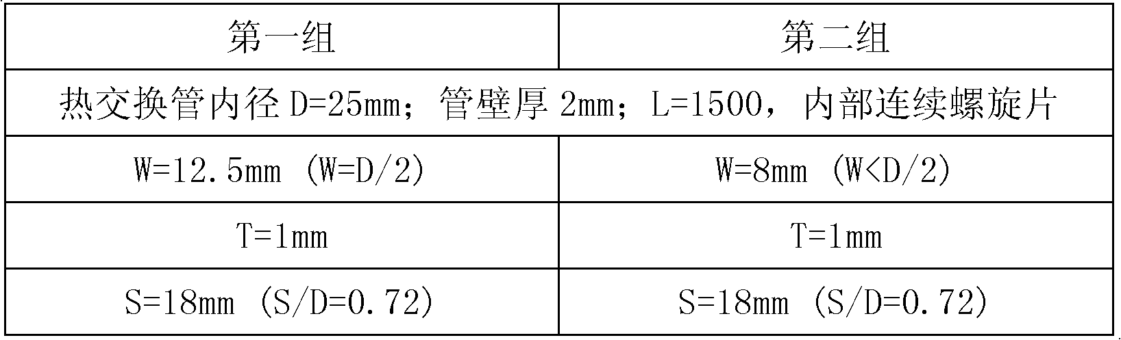
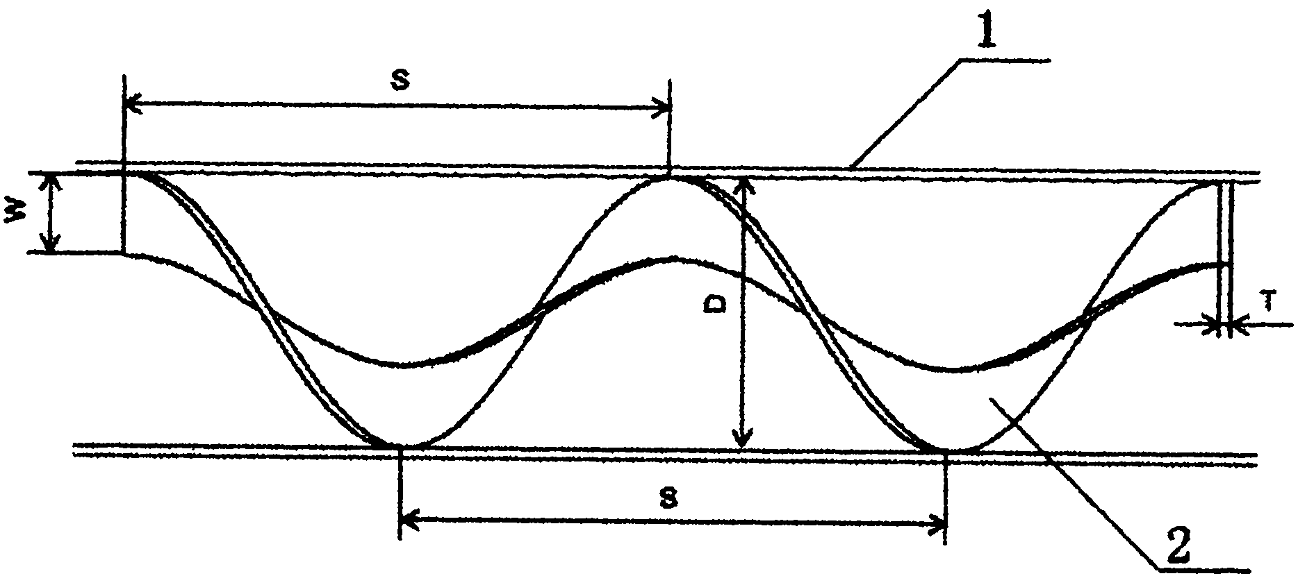
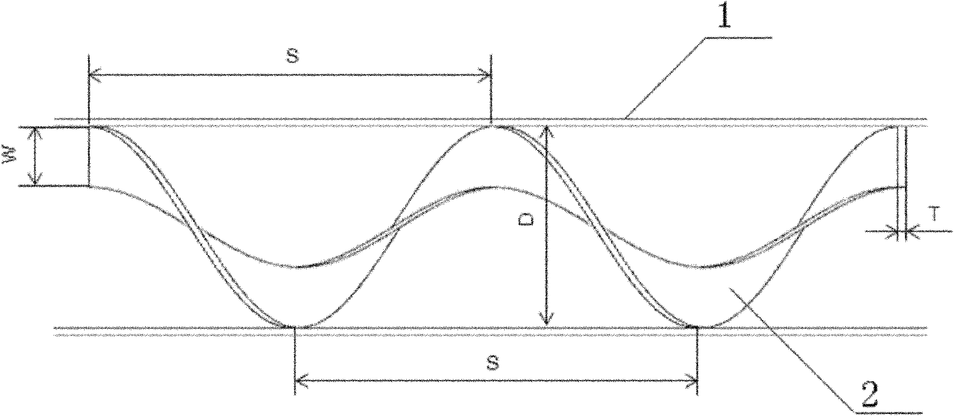
The invention relates to a heat exchange tube internally provided with spiral fins and application thereof. The heat exchange tube internally provided with the spiral fins comprises a heat exchange tube (1) and is characterized in that the heat exchange tube (1) is internally provided with the spiral fins (2) which are spiral; and the spiral fins (2) are distributed in the form of one or more sections along the axial direction at the inner side in the heat exchange tube (1). Meanwhile, the heat exchange tube internally provided with the spiral fins can be arranged in a radiation section furnace tube of an ethylene cracking furnace and can also be arranged in other heat exchangers, such as a shell-and-tube heat exchanger. The heat exchange tube achieves the purposes of increasing the heat transfer efficiency, strengthening the heat transfer effect, reducing coking, reducing the capacity consumption and increasing the life cycle of the equipment. Meanwhile, the spiral design also reduces the washing and abrading phenomena of high-speed fluid in the heat exchange tube to the interior of the tube body, thereby the heat transfer effect is further strengthened.
Description
A heat exchange tube with built-in spiral fins and its application technical field The invention relates to a heat exchange tube and its application. More specifically, the invention relates to a heat exchange tube with built-in spiral fins and its application in an enhanced heat transfer furnace tube of an ethylene cracking furnace, which belongs to the field of energy and chemical industry. Background technique Ethylene cracking furnace is an important equipment in petrochemical industry, mainly used for heating cracking raw materials to realize cracking reaction. The cracking reaction of high temperature, short residence time and low hydrocarbon partial pressure is the key to improving the cracking selectivity and cracking depth, and then improving the yield of key chemical products such as ethylene and propylene. Therefore, the cracking reaction process requires a lot of heat, making cracking Furnace is a major energy consumer of ethylene plant, and its energy consumpt...
Claims
Login to View More Application Information
Patent Timeline
 IPC IPC(8): F28F13/06F28F13/02C10G9/20
Inventor 倪志宇王学生黄志荣蒋晓东李培宁代晶晶
Owner EAST CHINA UNIV OF SCI & TECH