Core column component of winding type pasted electronic element and manufacturing method thereof

A technology of electronic components and manufacturing methods, applied in the direction of electrical components, inductor/transformer/magnet manufacturing, transformer/inductor magnetic core, etc., can solve the problems of limited applicable wire diameter, increase the overall height of the product, etc., to facilitate surface mount , Improve product reliability, good coplanarity

Active Publication Date: 2011-06-15
SHENZHEN SUNLORD ELECTRONICS
View PDF4 Cites 12 Cited by
  • Summary
  • Abstract
  • Description
  • Claims
  • Application Information

AI Technical Summary

Problems solved by technology

This method is applicable to a limited wire diameter, generally no more than 0.06mm, and will significantly increase the overall height of the product

Method used


Image

  • Core column component of winding type pasted electronic element and manufacturing method thereof
  • Core column component of winding type pasted electronic element and manufacturing method thereof
  • Core column component of winding type pasted electronic element and manufacturing method thereof

Examples


specific Embodiment approach 1

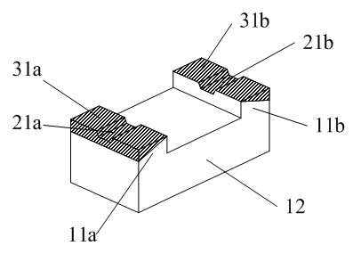
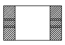
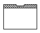
[0030] like Figure 1 to Figure 2c As shown, a stem part of a wire-wound mounted electronic component includes a stem and external electrodes 31a, 31b. The stem main body 12 of the right end protrusion 11b; the left end protrusion 11a is provided with a groove 21a, and the right end protrusion 11b is provided with a groove 21b; the external electrode 31a continuously covers the upper surface of the left end protrusion 11a and the groove 21a On the surface of the outer electrode 31b, the outer electrode 31b is continuously covered on the upper surface of the right end protrusion 11b and the surface of the groove 21b. In order to make the stem component more stable after mounting and increase the contact area between the outer electrode and the installation motherboard, this specific implementation Part of the side surfaces of the left end protrusion 11a and the right end protrusion 11b of the stem member of the above method are also covered with the external electrode layer.

...

specific Embodiment approach 2

[0033] like Figure 3 to Figure 4c As shown, the stem part of the wire-wound mount electronic component in this specific embodiment is a magnetic core part, including a stem and an external electrode, and its overall structure is the same as that of the wire-wound mount electronic component in Embodiment 1. The components of the core column are the same, the difference is that the core column in this specific embodiment adopts a magnetic core made of ferrite.

[0034] like Figures 5 to 6 As shown, the manufacturing process flow of the stem component of the wire-wound mounted electronic component in this specific embodiment is as follows:

[0035] Step S1: a mold preparation process, that is, a process of prefabricating the mold required for forming the magnetic core. As an example, high-hardness, wear-resistant tungsten steel can be processed into the shape of the magnetic core shell by a lathe to form the mold protrusion required for making the magnetic core groove, and th...

specific Embodiment approach 3

[0045] like Figure 7 As shown, the difference between this specific embodiment and the stem part of the wire-wound SMT electronic component in Embodiment 1 is that the grooves 21a and 21b of this specific embodiment are respectively located in the middle of the left end protrusions 11a and 11b, and Intersects the electrode plane at an acute angle.


PUM

PropertyMeasurementUnit
thicknessaaaaaaaaaa

Abstract

The invention discloses a core column component of a winding type pasted electronic element and a manufacturing method of the core column component. The core column component comprises a core column and an external electrode, wherein the core column comprises a left-end convex part, a right-end convex part and a core column body which is connected with the left-end and right-end convex parts, grooves are arranged on both the left-end and right-end convex parts, and the external electrode continuously covers the upper surfaces of the left-end and right-end convex parts and the surface of the groove. The method of the invention is used for manufacturing the core column component. By means of the core column component of the invention, coil ends with various wire diameters can be conveniently welded without increasing the overall height of the product.

Description

technical field [0001] The invention relates to mounted electronic components, in particular to a stem part of a wire-wound mounted electronic component and a manufacturing method thereof. Background technique [0002] With the development of electronic technology, electronic components are gradually developing toward chip type, miniaturization, high current, and high reliability, requiring products to be able to adapt to high-speed dense placement. [0003] For ordinary wire-wound SMD products, the ends of the coil are generally electrically and continuously connected to the two electrodes of the core post by thermocompression welding or immersion tin. When the wire diameter is thicker, it is difficult for both ends of the coil to be completely buried in the metal layer of the stem electrode, and the wire will be significantly higher than the plane of the stem electrode, resulting in uneven electrode surfaces of the product, which will affect the soldering performance of th...

Claims


Application Information

Patent Timeline
Patent Type & Authority Applications(China)
IPC IPC(8): H01F27/24H01F3/08H01F1/36H01F41/02
Inventor 赵卫北黄敬新高海明
Owner SHENZHEN SUNLORD ELECTRONICS
Why Eureka
Try Eureka